Hi Jeff,
I don’t understand most of your arguments regarding the use of mathematical mode and circuit simulations due to the fact that:
1.
My discussions over the last 4-5 weeks was about the channel only which is connectors and cables.
1.1
For that I did a mathematical model in order to find the best physical numbers of Channel P2PRUNB and Rdiff that will cover our uses cases of the channel only! and will be a
complete spec that I can count on it for every channel installations in the field including those we believe that they are unrealistic due to the simple fact that we cannot control it nor can force it. This work I have finalized few days ago and the plane
is to have a motion to use its results to close the TBDs.
2.
When you discuss about maximum current etc. it is related to the whole system including PSE PI circuitry, and PD PI circuitry and the channel ( connectors and cable only).
For this we did simulation per the electrical model shown in the adhoc with the data base attached to it. This data base is changing over time per the inputs we get and it is one of the sources for results
differences over time. In addition, there may be some differences in the models people used. My and Christian model is almost the same. Ken may be has different one and you probably has different one. I hope that all of us will use the same model as in the
adhoc documents so we can compare results for the same given components.
3.
To me, Item 2, is ancient history.
We have all the information we need. We understand fully the behavior under different conditions.
4.
We are now in different discussions such of: What are the minimum number of parameters that are needed to fully and completely specify the PSE PI and PD PI unbalance.
For that question, we need to describe mathematically
(in global parameters i.e./e.g. Rmin, Rmax Rdiff, P2PRUNB, Vdiff) how the PSE PI, PD PI and channel are related to end to end channel unbalance behavior. These are the discussions and presentations related to PSE and PD models that Ken showed in his
presentation and I have shown in my slides at the adhoc.
Why we need to do it with mathematical _expression_ first before we jumping to simulations:
It is because that when you see an equation and you need to find its solution, you see immediately how many parameters you need in order to find the solution.
Example: What are the parameters from the list above are needed to limit the max pair current given the channel and PD PI parameters.
You may solve this question by simulation but it is not the sure way that guarantee that you didn’t miss a parameter that remain undefined which will cause later interoperability issues.
Now if all the above clear (it is a summary of what we did, what we do now and what we are going to do and why) I'll address your question:
You asked:
Look at your last ad hoc report to the task force in May 2014.
The ad hoc report on page 31 shows that a 2 connector model with 100m as the highest current of 1099.57ma at 75W.
The report shows 989.47mA at 0.15m.
Yair: If you asking why in Christian report he got more current at 100m than in 1m it could be due to two reasons:
a)
In this report, Christian may use used components at the PSE PI and PD PI that generated lower system P2PRUNB. As a result the maximum current is obtained at 100m
and not at 1m.
b)
You need to check with Christian if he use constant power sink model in the PD. It may change results too.
Once you have these data, you can check it with simulations and get your answer.
The general behavior must obey to the below equation (which is not the mathematical system equation, it is just calculating the maximum pair current when the P2PRUNB is given.
See the word "OR" below.
Imax(Channel Length) =0.5*(1+alfa(Channel Length)/2
Alfa is complex _expression_ of P2PRUNB.
It(Channel length) is also complex. It include system variable such PSE voltage, Channel resistance, PD power and PSE PI and PD PI components.
The behavior of I max is according to below terms.
You asked:
At that meeting we openly speculated on how this could be during the question and answer period.
Yair: Not clear what "how it could be?". Do you mean higher current at the 100m?. Numbers can be any per data and models used. See above if now it answers your question.
I also don’t remember this discussion. Any how these number could be pending data and model used.
-----------------
You asked:
Please look into the negative current.
Yair: I need the simulation model that you used. I mean not to block diagram as sent below. I mean the full electrical circuit. Without it it will be hard to track what happen and
why you got negative current.
-----
Given the large voltage offsets in this current diode model, there should be negative currents if the simulation is set up properly.
Yair: What do you mean by that "if simulation is setup properly?". What could be an example of simulation that was not setup properly that may affect not seeing negative current?
------
The negative current problem was raised in my presentation to the ad hoc.
Yair: Yes I remember it. But I looked again in your presentation and I couldn’t find this data. I am wondering if it is real problem or a result of simulation not setup properly?.
I am trying to understand firs before I jump to simulation and spend time on it. Once I understand it, I may not need the simulation.
---
Here is the circuit I use from my presentation at the ad hoc:
Yair: Yes I know. It is not explaining you spice circuit (resistors, diode, DC/DC PSE etc. locations of loads, current loops, reference measurement points etc. so I see first if all is good.)
--------------
The negative current is the only possible result when you use your simple diode model with very high voltage offsets and low overall resistance which is the case with a short
channel.
Yair: When you say my simple diode model, do you mean to voltage source and resistor?
----------------------
It is simply Ohms law and it is picked up by the simulation.
Yair: You may be correct but still it is not clear to me how you get a net negative current. Please send more details about the current on each per and were you saw the negative current.
This with the electrical circuit will help to understand this.
-------------------
I have never seen the current in all 4 pairs reported in this ad hoc before my simulation results. It would be useful for the group to be able to see the data and sanity check
your results.
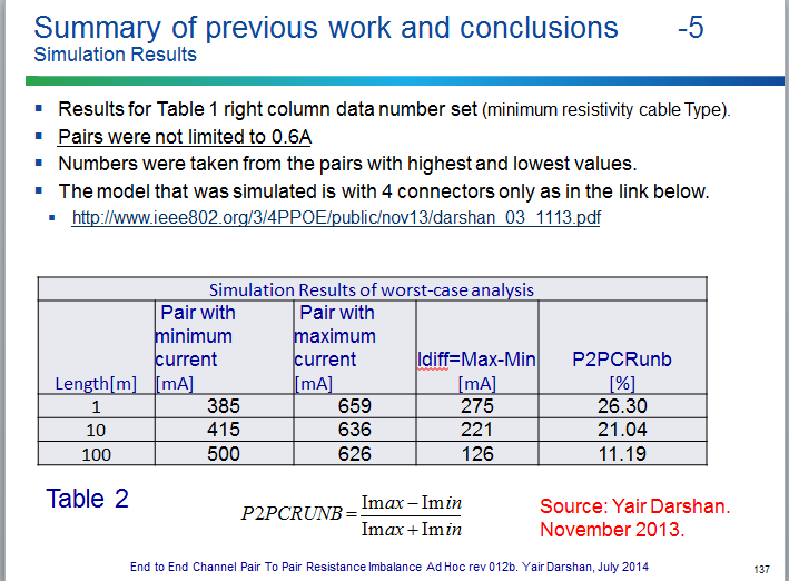
Yair: You can find such data at my presentation from November 2013.
http://www.ieee802.org/3/4PPOE/public/nov13/darshan_03_1113.pdf
This presentation was with Vdiff=0. I can check with Vdiff>0. What was your Vdiff?. Then we can compare.
--------------------
Again, your math model greatly oversimplifies the problem. Spice is a much better tool for circuit analysis.
Yair:
(1)
I hope that you now understand that you misunderstood what I did and what I am doing.
(2)
You are in a phase of work were you are running simulations on the a complete system that we already been there a year ago, and now I am working on
other milestones of our project.
I am not saying that running again and again more and more system simulations is not required. I believe that all inputs are good and adds value to our work and also when
data is changed, you need to rerun to update the result data base. All is fine and valuable.
(3)
My math addresses different issues that are hard to understand in spice simulations. For example: Rdiff (and Vdiff) cannot be sufficient to specify
PSE PI or PD PI. And there are many more examples.
(4)
Yes, spice is perfect for circuit analysis. If you have a spec, and you want to build a circuit that meet the spec. This is great.
But first you need spec. And spec is done not by circuit analysis tools such spice. It could be but it is not efficient way. it is done by tools such MATLAB/SIMULINK etc.
OR by deriving your system equations that its major benefit is deep understanding of the subject so we can generate specs. Once you have it, fill it with components and run spice.
What you did with spice and what we did a year ago is running simulations on a given circuit. It is hard to derive a spec from it. It helps to set your limits but limits are
part of the spec. First we need to define the parameters that must be in the spec and without them the spec is not complete.
(5)
I have spent time to explain all of it above. I hope it helps.
Best regards.
Yair
Regards
Yair
From: Jeff Heath [mailto:jheath@xxxxxxxxxx]
Sent: Tuesday, July 08, 2014 10:00 PM
To: Darshan, Yair; STDS-802-3-4PPOE@xxxxxxxxxxxxxxxxx
Subject: RE: [802.3_4PPOE] End to End Channel Pair to Pair Unbalance Ad Hoc Presentation
Yair,
I am looking at your most recent data presented at the last task force meeting in Norfolk.
Look at your last ad hoc report to the task force in May 2014.
The ad hoc report on page 31 shows that a 2 connector model with 100m as the highest current of 1099.57ma at 75W.
-----
The report shows 989.47mA at 0.15m.
At that meeting we openly speculated on how this could be during the question and answer period.
Please look into the negative current. Given the large voltage offsets in this current diode model, there should be negative currents if the simulation is set up properly. The
negative current problem was raised in my presentation to the ad hoc.
Here is the circuit I use from my presentation at the ad hoc:
The negative current is the only possible result when you use your simple diode model with very high voltage offsets and low overall resistance which is the case with a short
channel. It is simply Ohms law and it is picked up by the simulation. I have never seen the current in all 4 pairs reported in this ad hoc before my simulation results. It would be useful for the group to be able to see the data and sanity check your results.
Again, your math model greatly oversimplifies the problem. Spice is a much better tool for circuit analysis.
Regards,
|
Jeff Heath |
|
|
|
|
|
paper: |
402 East Carrillo Street, Suite D |
|
|
Santa Barbara, California 93101 |
|
voice: |
805.965.6400 |
|
fax:
|
805.965.1701 |
|
computer: |
|
|
|
Thank you.
From: Darshan, Yair [mailto:YDarshan@xxxxxxxxxxxxx]
Sent: Tuesday, July 08, 2014 4:13 AM
To: STDS-802-3-4PPOE@xxxxxxxxxxxxxxxxx
Subject: Re: [802.3_4PPOE] End to End Channel Pair to Pair Unbalance Ad Hoc Presentation
Jeff,
1.
The possibility of high current at short cable as opposed to the expectation of high current at 100m is known to us from our work on July 2013 and adhoc meeting
and February 2013 from the analytical analysis. It depends on End to End Channel P2PRUNB and the absolute resistance of each component in the system. Please see Annex B from adhoc material attached below with simulations that confirmed it.
In Short it depends on the following:
2.
In Christian and my work a year ago, We checked results at channel <=1m and 100m with the database components at that time and I got higher current at 1m.
3.
If your PSE PI and PD PI unbalance is very high, yes, you should expect to much higher current at the short channel as expected by the system equation and confirmed
in simulation.
4.
Regarding negative current. I don’t remember that I saw something similar. Not clear to me how it can be?, can you send the spice drawing to check if there are
issues with the model?
Regards
Yair
The following is per older data base, 4 connector channel model with PSE and PD PI.
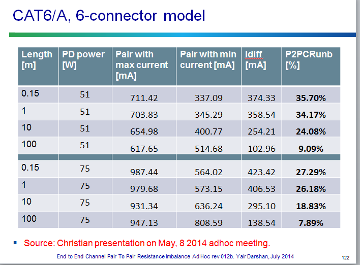
The following is per older data base, 6 connector channel model with PSE and PD PI.
From: Jeff Heath [mailto:jheath@xxxxxxxxxx]
Sent: Tuesday, July 08, 2014 2:59 AM
To: STDS-802-3-4PPOE@xxxxxxxxxxxxxxxxx
Subject: [802.3_4PPOE] End to End Channel Pair to Pair Unbalance Ad Hoc Presentation
From: Jeff Heath [mailto:jheath@xxxxxxxxxx]
Sent: Monday, July 07, 2014 4:43 PM
To: STDS-802-3-4PPOE@xxxxxxxxxxxxxxxxx
Subject: RE: [802.3_4PPOE] End to End Channel Pair to Pair Unbalance Ad Hoc Presentation
All,
This is some interesting data, with the current set of assumptions using my PI definitions and Wayne’s channel, Wayne A is the problem child for maximum pair current. It should
be noted that the current diode model cause negative current to flow on both the high side and low side pairs. I believe we need to address this diode model.
Yair and Christian,
Did you not see negative current in your simulations on either the high side or low side pairs?
Regards,
|
Jeff Heath |
|
|
|
|
|
paper: |
402 East Carrillo Street, Suite D |
|
|
Santa Barbara, California 93101 |
|
voice: |
805.965.6400 |
|
fax:
|
805.965.1701 |
|
computer: |
|
|
|
From: Larsen, Wayne [mailto:WLARSEN@xxxxxxxxxxxxx]
Sent: Monday, July 07, 2014 6:13 AM
To: STDS-802-3-4PPOE@xxxxxxxxxxxxxxxxx
Subject: Re: [802.3_4PPOE] End to End Channel Pair to Pair Unbalance Ad Hoc Presentation
Hello Yair,
It seems to me, you are trying to solve two problems:
-
You want to know the absolute worst case cabling pair-to-pair DC resistance unbalance
-
You want to know what the unbalance actually is, more accurately than the worst case.
I think the proposal in red addresses the first problem.
For the second problem, I think you can use the four use cases I proposed, and the values of the cabling components I provided, or others you think are right. You can add more use cases, but you should not add
unreasonable ones.
Wayne
7/7/14
From: Darshan, Yair [mailto:YDarshan@xxxxxxxxxxxxx]
Sent: Thursday, July 03, 2014 1:55 PM
To: Larsen, Wayne; STDS-802-3-4PPOE@xxxxxxxxxxxxxxxxx
Subject: RE: [802.3_4PPOE] End to End Channel Pair to Pair Unbalance Ad Hoc Presentation
I need the 0.1 ohm, since this is the correct number and it gives me better channel unbalance.
I need the 0.2 ohm to address your use case #2 which is valid use case but yet crosses the 7%.
I need explicit text that will prevent me to argue with future test house when they may use unrealistic channel installations.
What I offer is covering what your are proposing but not the opposite.
Yair
From: Larsen, Wayne [mailto:WLARSEN@xxxxxxxxxxxxx]
Sent: Thursday, July 03, 2014 9:16 PM
To: Darshan, Yair; STDS-802-3-4PPOE@xxxxxxxxxxxxxxxxx
Subject: RE: [802.3_4PPOE] End to End Channel Pair to Pair Unbalance Ad Hoc Presentation
Hi Yair,
Why not just,
The maximum DC resistance unbalance between pairs of a channel shall not exceed 0.200 Ohms or 7 %, whichever is greater.
That would avoid lengthy sentence about ignoring it when the resistance is less than .200 Ohms.
Wayne
7/3/14
From: Darshan, Yair [mailto:YDarshan@xxxxxxxxxxxxx]
Sent: Thursday, July 03, 2014 1:02 PM
To: STDS-802-3-4PPOE@xxxxxxxxxxxxxxxxx
Subject: Re: [802.3_4PPOE] End to End Channel Pair to Pair Unbalance Ad Hoc Presentation
Hi Wayne and all,
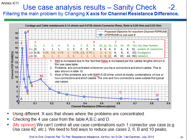
Please see slide below from my presentation on Tuesday adhoc which addresses your question.
You can see ,as expected, the peaks of the "nonrealistic use cases"
and one realistic use case B are happens when channel Resistance difference is below 0.2 ohm.
Also consider the fact that the connectors that I have use in the simulations are with Rmin=30 miliOhm and Rmax=50miliOm which means Rdiff=80miliom max for 4 connectors or 40miliokms for 2 connectors etc. which
you can see from the plot that the peaks of the "nonrealistic use cases" is below 40 miliOhm or so for <=2 connectors.
Now what I thought to do with it is to have a text saying that:
I am proposing the following text to fix all issues:
The Channel P2PRUNB shall not acceded 7% or maximum pair to pair resistance difference of 0.1 ohm whichever is greater.
Channel P2PRUNB of a channel with maximum pair to pair resistance difference of 0.2 ohm may be ignored.
(Or instead of "may be ignored", shall be limited to 25% max. (25% max is the mathematically upper bound of P2PRUNB of any number of connectors with zero cables with the parameters we used)
I'll appreciate, any comments on this.
Yair
From: Larsen, Wayne [mailto:WLARSEN@xxxxxxxxxxxxx]
Sent: Thursday, July 03, 2014 4:13 PM
To: Darshan, Yair; STDS-802-3-4PPOE@xxxxxxxxxxxxxxxxx
Subject: RE: [802.3_4PPOE] End to End Channel Pair to Pair Unbalance Ad Hoc Presentation
Hi Yair,
Would the existence of a spec, such as, not more than the max of .2 Ohms (or .1 Ohms) or 7% (or 6%) achieve this closure?
Wayne
7/3/14
From: Darshan, Yair [mailto:YDarshan@xxxxxxxxxxxxx]
Sent: Thursday, July 03, 2014 8:01 AM
To: Larsen, Wayne; STDS-802-3-4PPOE@xxxxxxxxxxxxxxxxx
Subject: RE: [802.3_4PPOE] End to End Channel Pair to Pair Unbalance Ad Hoc Presentation
Hi Wayne,
Wayne I agree that we shouldn't be worried about.
The question is how to convert "don’t worry it is unrealistic in real installations" to "don’t worry, the spec says A, B, C" therefore don’t worry.
I am looking for some text/other means to close this hole in the future spec so if someone during tests will have "unrealistic channel" that is used in the lab and not in real life installation I can point him to the spec and say
"this is wrong setup ..and this is why, see the spec." .
I am working on such closure.
Yair
From: Larsen, Wayne [mailto:WLARSEN@xxxxxxxxxxxxx]
Sent: Thursday, July 03, 2014 3:31 PM
To: Darshan, Yair; STDS-802-3-4PPOE@xxxxxxxxxxxxxxxxx
Subject: RE: [802.3_4PPOE] End to End Channel Pair to Pair Unbalance Ad Hoc Presentation
My opinion would be that the unrealistic use cases do not need to be worried about.
From: Darshan, Yair [mailto:YDarshan@xxxxxxxxxxxxx]
Sent: Thursday, July 03, 2014 2:12 AM
To: Larsen, Wayne; STDS-802-3-4PPOE@xxxxxxxxxxxxxxxxx
Subject: RE: [802.3_4PPOE] End to End Channel Pair to Pair Unbalance Ad Hoc Presentation
Hi Wayne,
This solution, filters the "unrealistic use cases" that were resulted from short cables.
How it helps?
If we set a limit for the channel for 7%, and a user did use cabling and connectors combinations that is considered "not typical use case" or even "not realistic use case" and he got 12% it will be an issue for
him. The spec says A and he got B.
This filters all the results of B which are not relevant to him when the channel is tested as standalone part.
The justification for this approach is, when the channel is connected to a system, and the channel uses short cables, the End to End current/resistance unbalance will be dominant since their unbalance is higher
than the channel.
This is one of the solutions from the table.
There is 5th solution that in after our adhoc meeting Sterling and I were discussing and I am working on its details.
Regards
Yair
From: Larsen, Wayne [mailto:WLARSEN@xxxxxxxxxxxxx]
Sent: Thursday, July 03, 2014 6:09 AM
To: Darshan, Yair; STDS-802-3-4PPOE@xxxxxxxxxxxxxxxxx
Subject: RE: [802.3_4PPOE] End to End Channel Pair to Pair Unbalance Ad Hoc Presentation
Hi Yair,
You showed a spreadsheet of four possible solutions, and one of them was to measure the DC resistance unbalance of the cabling channel with resistors in series with it.
What is the problem these solutions are solving?
Wayne
7/2/14
From: Darshan, Yair [mailto:YDarshan@xxxxxxxxxxxxx]
Sent: Wednesday, July 02, 2014 7:15 PM
To: Larsen, Wayne; STDS-802-3-4PPOE@xxxxxxxxxxxxxxxxx
Subject: RE: [802.3_4PPOE] End to End Channel Pair to Pair Unbalance Ad Hoc Presentation
H Wayne,
Your question Is not clear to me can you elaborate?
Yair
From: Larsen, Wayne [mailto:WLARSEN@xxxxxxxxxxxxx]
Sent: Wednesday, July 02, 2014 11:38 PM
To: STDS-802-3-4PPOE@xxxxxxxxxxxxxxxxx
Subject: Re: [802.3_4PPOE] End to End Channel Pair to Pair Unbalance Ad Hoc Presentation
Hi Yair,
I was trying to ask, what problem is being solved by this?
Wayne
7/2/14
From: Jeff Heath [mailto:jheath@xxxxxxxxxx]
Sent: Wednesday, July 02, 2014 11:25 AM
To: STDS-802-3-4PPOE@xxxxxxxxxxxxxxxxx
Subject: Re: [802.3_4PPOE] End to End Channel Pair to Pair Unbalance Ad Hoc Presentation
Please announce when and why the ‘formal meeting’ has ended in the future.
Regards,
|
Jeff Heath |
|
|
|
|
|
paper: |
402 East Carrillo Street, Suite D |
|
|
Santa Barbara, California 93101 |
|
voice: |
805.965.6400 |
|
fax:
|
805.965.1701 |
|
computer: |
|
|
|
From: Darshan, Yair [mailto:YDarshan@xxxxxxxxxxxxx]
Sent: Wednesday, July 02, 2014 9:00 AM
To: Jeff Heath; STDS-802-3-4PPOE@xxxxxxxxxxxxxxxxx
Subject: RE: [802.3_4PPOE] End to End Channel Pair to Pair Unbalance Ad Hoc Presentation
I meant that we continue to discuss after the time of the forma meeting. The formal meeting ends when there is not sufficient attendees or someone ask to finish on time, or most of the group agrees to continue,
so after that time we can continue discussion whit out having decisions.
Yair
From: Jeff Heath [mailto:jheath@xxxxxxxxxx]
Sent: Wednesday, July 02, 2014 6:16 PM
To: Darshan, Yair; STDS-802-3-4PPOE@xxxxxxxxxxxxxxxxx
Subject: RE: [802.3_4PPOE] End to End Channel Pair to Pair Unbalance Ad Hoc Presentation
What do you mean by formal ad hoc meeting?
Regards,
|
Jeff Heath |
|
|
|
|
|
paper: |
402 East Carrillo Street, Suite D |
|
|
Santa Barbara, California 93101 |
|
voice: |
805.965.6400 |
|
fax:
|
805.965.1701 |
|
computer: |
|
|
|
From: Darshan, Yair [mailto:YDarshan@xxxxxxxxxxxxx]
Sent: Wednesday, July 02, 2014 3:53 AM
To: Jeff Heath; STDS-802-3-4PPOE@xxxxxxxxxxxxxxxxx
Subject: RE: [802.3_4PPOE] End to End Channel Pair to Pair Unbalance Ad Hoc Presentation
Thanks Jeff.
I am working on this direction too and few others that we discuss after the formal 1 hour time of the adhoc meeting.
Yair
From: Jeff Heath [mailto:jheath@xxxxxxxxxx]
Sent: Tuesday, July 01, 2014 7:53 PM
To: STDS-802-3-4PPOE@xxxxxxxxxxxxxxxxx
Subject: Re: [802.3_4PPOE] End to End Channel Pair to Pair Unbalance Ad Hoc Presentation
Yair,
The entire principle of adding balanced resistance to test imbalanced channel resistance does not represent any real system. PSE PI and PD PI will add imbalance in worst case
analysis. At the end of the day only full worst case analysis using all three components will give us the correct worst case maximum current
Regards,
|
Jeff Heath |
|
|
|
|
|
paper: |
402 East Carrillo Street, Suite D |
|
|
Santa Barbara, California 93101 |
|
voice: |
805.965.6400 |
|
fax:
|
805.965.1701 |
|
computer: |
|
|
|