Colleagues,
As we discussed in Berlin, our intention is to request advancing the draft to Working Group ballot at the July plenary. To do this, the draft we generate out of May will be the WG preview draft. While it is possible to change the draft at July meeting, I’d rather not do that unless absolutely necessary.
To that end, this comment cycle needs to address all open issues. I have searched the draft for TBDs and we still have them. We cannot go to WG ballot with TBDs in the draft. Please look all these over carefully and determine what course of action should be taken. It is perfectly acceptable to choose a “target” value at this time if we do not have a final value. We can finalize these values during WG ballot, and even SB if necessary.
Her are the TBDs I found. Feel free to do your own search in case I missed any.
Page 79:
RFER_CNT_LIMIT
TYPE: TBD
Number of Reed Solomon frames with uncorrectable errors.
RFRX_CNT_LIMIT
TYPE: TBD
Number of Reed Solomon frames received over bit error rate interval.
Page 103:
97.5.3 Transmitter electrical specifications
The PMA provides the Transmit function specified in 97.4.2.2 (?) in accordance with the electrical specifications
of this clause. The PMA shall operate with AC coupling to the MDI. Where a load is not specified,
the transmitter shall meet the requirements of this Clause with a 100 (TBD) resistive differential load connected
to the transmitter output.
Page 122:
The PHY current health is sent to the link partner on a per OAM frame basis using the SNR<1:0> bits as
described in 97.7.2.2.1. It lets the link partner have an early indication of potential problems that may cause
the PHY to drop link or have high error rates.
If EEE is implemented there may be a case where a PHY's receiver can no longer keep good SNR based on
quiet/refresh cycles. Instead of dropping link, the PHY can attempt to recover by forcing the link partner to
exit LPI in its egress direction so that the PHY can receive normal activity to recover. This is done by transmitting
SNR<1:0> with a value of 01.
If a PHY receives SNR<1:0> set to 01 by its link partner, then it cannot enter into LPI in the egress direction.
If the PHY is already in LPI then the PHY must immediately exit LPI. The rules of exiting and entering LPI
are discussed in TBD.
Page 132:
97.8.2.3 MDI fault tolerance
The wire pair of the MDI shall, under all operating conditions, withstand without damage the application of
short circuits of any wire to the other wire of the same pair or Ground potential or positive voltages of up
±50 V for an indefinite period of tune and shall resume normal operation after the short circuit(s) are
removed. The magnitude of the current through such a short circuit shall not exceed 150 mA (or TBD).
Page 144:
Table 98–1—DME page timing summary
Parameters Min Typ Max Units
T1 Transmit position spacing (period) 29.997 30 30.003 ns
T2 Clock transition to clock transition 59.8 60 60.2 ns
T3 Clock transition to data transition (data = "" 29.9 30 30.1 ns
T4a +1 to -1 or -1 to +1 transitions in a DME page 79 - 143 -
T4b 0 to +/1 or +/-1 to 0 transitions in a DME page 2 2 2 -
T5 DME page width 4619 4620 4621 ns
T6 DME Manchester violation delimiter width TBD TBD TBD ns
Page 161:
98.5.3 State diagram counters
remaining_ack_cnt
A counter that may take on integer values from 0 to 3 (TBD). The number of additional link codewords
with the Acknowledge Bit set to logical one to be sent to ensure that the link partner receives
the acknowledgment.
Values:
not_done: positive integers between 0 and 2 (TBD) inclusive.
done: positive integer 3 (default).
init; counter is reset to zero.
Page 165:
98.6 Electrical specifications
TBD
Page 169:
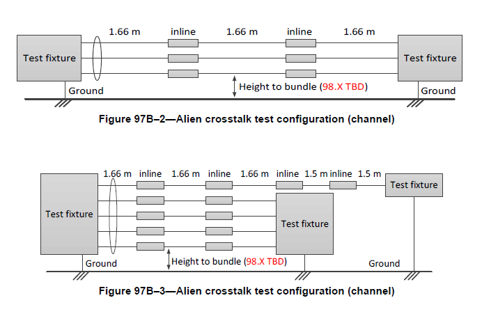
97B.1.1 Alien crosstalk test configurations
The limits for PSANEXT and PSAACRF are based on the alien crosstalk test configurations in Figure 97B–
2, Figure 97B–3, and Figure 97B–4. The automotive link segment test configurations are derived from two
automotive industry use cases representative of common scenarios.
Measurements to be performed at 23°C ± 5°C relative humidity 25% – 75%.
Multiport test fixtures shall be used for multiport link segments. The number of disturbing ports to be
included in the power sum calculation is dependent on the configuration. Significant connectors may be
located in the same or other mounting systems in close proximity and shall be assessed as follows. For any
given configuration, the determination of which ports to be included can be made based on the ANEXT loss
contribution to the disturbed port. If at any frequency point the ANEXT measurement is less than TBD, then
the entire ANEXT loss and PSAACRF response of that connector combination shall be included in the overall
power sum result.
Page 170:
Figure 97B–1—TBD
Editors Note (to be removed prior to publication): indicate height in all figures are to be consistent with
Annex 97A test setup
Page 171:
Besides, the TBDs, please look the draft over and identify any missing areas and supply text as part of the commenting process.
Regards,
Steve
Steven B. Carlson
Chair, IEEE P802.3bp 1000BASE-T1 PHY Task Force
http://www.ieee802.org/3/bp/index.html
Executive Secretary, IEEE 802.3 Working Group
http://grouper.ieee.org/groups/802/3/index.html
President
High Speed Design, Inc.
Portland, OR
scarlson@xxxxxxxxxxxxx