Hi John,
Thank you for your comments.
Yes, I agree with your observations, the ZDW distribution is the most sensitive parameter affecting FWM probability (for the worst-case polarization ‘XXXX’). Other parameters such as optical power have less impact on probability and only
start being relevant when the fiber lambda0 and channel wavelengths are aligned to generate FWM.
The fiber distribution you are using is very close to what I presented. I have calculated our CDF for <1306nm, they are almost the same, mine is 1.8e-4 and yours 2.3e-4.
Regarding your question on the fraction of ZDW in my analysis < 1306nm, I got 17 out of 1e5 iterations with lambda0 <1306nm (very close to the calculated CDF of 1.8e-4). If I had to see a 7% that you mentioned, I should have seen a single
instance (17*0.07= ~1). The random nature of the MC analysis could have just missed it. I will work on parallelizing my code to run 1 or 2 orders of magnitude more iterations for better statistics. How many iterations did you run?
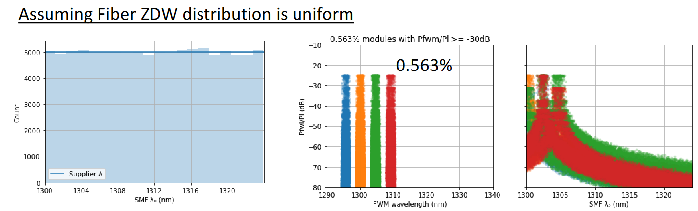
For the ratio of FWM below 1306nm one can also look at our October contribution slide#7 with uniform distribution which has 25% of all iterations with lambda0 <1306nm. All instances with high FWM were for lambda0 <1306nm, therefore, you
can say that the conditional probability of FWM penalty given a fiber lambda0 <1306nm is 4x0.563% = 2.252% (for Pfwm/Pl<-30)
Thank you again for your comments. We look forward to continuing working with you on the FWM analysis. For instance, I am interested on your input to narrow down the reduction on Pfwm/Pl with ‘XYYX’ (at certain probability), and also the
impact of the distance between splices that Maxim presented in November.
Regards,
Roberto
From: John Johnson <jejohnson@xxxxxxxx>
Sent: Thursday, December 1, 2022 5:56 PM
To: STDS-802-3-B400G@xxxxxxxxxxxxxxxxx
Subject: [EXTERNAL]: Re: [802.3_B400G] Further questions for clarification
Hi Roberto,
I've been running 800G-LR4 Monte Carlo simulations with conditions very similar to yours, and I believe our conclusions are the same.
I found that the single most important parameter affecting the FWM outage probability is the assumed ZDW distribution. Using a Normal distribution with mean of 1313nm and sigma of 2.0nm, I had ~3e-4 of the fibers with ZDW < 1306nm. All
cases with ZDW > 1306nm had Pfwm/Psig < -35dB. Of those with ZDW < 1306nm, about 7% resulted in one or more channels with Pfwm/Psig > -35dB, for a LR4 module outage probability ~2e-5, which is a little higher than what you simulated. It can't be seen from
your chart on slide 4, so can you share what fraction of ZDW in your analysis, which resulted in no cases having Pfwm/Psig > -45dB, was < 1306nm?
I agree with you that the other simulation parameters have relatively smaller effects. I used an OMA distribution at 5dB ER with mean of 4.4dBm and sigma of 0.7dB, truncated at +2 and +5dBm. As you explained, a 1dB drop in the victim
channel power just shifts Pfwm/Psig up by 1dB, so this only has a small impact on the FWM outage probability. I used a slightly narrower LAN-WDM wavelength distribution based on 100G-LR4 experience (sigma = 57GHz, truncated at +/-170GHz) but that also has
only a small impact on the outage probability compared with your uniform (+/-200GHZ?) distribution assumption.
Regards,
John
On Wed, Nov 30, 2022 at 3:49 AM Peter Stassar <000017da312dfb6f-dmarc-request@xxxxxxxxxxxxxxxxx> wrote:
Hi Roberto,
Thanks a lot for your responses to my questions.
I will need some time to digest.
I would also expect this to be food for further questions and discussions.
Kind regards,
Peter
From: Roberto Rodes [mailto:roberto.rodes@xxxxxxxxxxxx]
Sent: Wednesday, November 30, 2022 6:13 AM
To: STDS-802-3-B400G@xxxxxxxxxxxxxxxxx
Subject: Re: [802.3_B400G] Further questions for clarification
Hi Peter,
I just realized my emails to the reflector have been getting rejected after my company II-VI rebranded as Coherent. I wrote (or tried) to the reflector last week asking for few days to get back to you. Sorry about that.
Thank you for your questions. There are a lot of questions indeed, but they are all fair. Some of them will deserve a future contribution and discussion, but for now, please read below our responses. Your questions are in black, our replies in red:
The first question which I raised was related to the range between OMAouter min (for max TDECQ), being 4.4 dBm, and OMAouter max, being 5 dBm, and how that would work in manufacturing, considering that during the cu project there were requests to raise that difference for the 400GBASE-LR4-6 from 2.1 to 2.5 dB.
It was my understanding that you acknowledged that this range was tighter than desirable and that it would need to be considered if it would be possible to raise the OMAouter max to 5.5 dBm.
Correct, and what I tried to say during the meeting is that the increase in OMAouter max does not necessarily require an increase on AOPmax. We will bring a contribution on this. For instance, on 400G-DR4, OMAouter max is higher than AOPmax.
This however raises further questions:
- Is a range of 1.1 dB for OMAouter at max TDECQ sufficient for setting in manufacturing, considering that +/- 0.25 dB is generally seen as a ballpark testing/reproducibility accuracy? Or would you need to go more towards a range of 2 dB which seems to be a ballpark minimum range of in-force IEEE optical PMDs.
We think 1.1-1.3dB is a reasonable OMA range @ TDECQmax considering that 800G-LR4 is based on LAN-WDM with cooled lasers. For reference, 400G-LR4 has 1.6dB OMA range@TDECQmax. EMLs and MZMs can use laser current as a nob to tune OMA while maintaining modulator condition. This was harder on traditional DMLs.
- Is a nominal Tx power of 5 dBm (OMAouter) achievable with current 200G PAM4 laser technology?
Yes, a nominal Tx power of 5 dBm (OMAouter) is achievable with current 200G PAM4 laser technology. We will bring some contribution on this in the future. For reference, EML for 802.3cn 200G-ER4 has an OMAouter range of 3.4 to 7.4dBm, 400G-ER8 has a range of 2.4 to 6.4 dBm, and 100G Lambda MSA’s 100G-ER1-40 has a range of 4.7 to 7.9dBm.
- Is a Receiver overload of 5.5 dBm achievable, considering that it would seem important to operate in all back-to-back configurations?
While we do not have overload data on 200G/lane TIAs yet, we expect no overload issue with 5.5dBm based on 100G/lane receivers. Receiver power is at TP3, before DMUX. For reference, 100G-LR1-20 specifies +6.6dBm AOP max for PIN-based receivers.
- Was is the impact on the FWM analysis by the raise in power by 0.5 dB?
The impact of 0.5dB higher OMA while maintaining AOPmax is modest, and it will be further quantified by using updated parameters later.
One intermediate question is related to the proposal for “Difference in launch power between any two lanes” to be “3 dB” max.
Is this average launch power or OMA? In the in-force specifications for 400GBASE-FR4 and 400GBASE-LR4-6 it is in OMA.
Per IEEE methodology, this delta is based on OMA. We will be more explicit on future contributions
Now back to my second question raised at last week’s meeting.
In your specification proposal on slide 6, you propose a max difference in launch power between any two lanes of 3 dB.
Shouldn’t we take that range into consideration for the analysis of FWM?
Yes, our simulations (used in rodes_3df_01a_2211) take into consideration of the power delta between lanes with a statistical approach. The margin on power in slide#5 is large, even a 3dB higher FWM crosstalk ( for a 3dB lower power victim lane) would still be negligible.
In October there was a presentation by your co-author Xiang Liu proposing to use a flat distribution of power per channel, whereas his first (and superseded) presentation assumed a range of 3 dB. Wouldn’t we need to use that range of 3 dB for the FWM analysis?
Yes, we need to consider the “worst-case max difference in launch power”, and do so with a statistical approach because such worst cases only occur with a small probability. This has been done in our contribution rodes_3df_01a_2211. I have run wider Tx OMA distributions with no significant change in results. We could add results into a later presentation.
Now, having been able to further look into the proposals in your updated presentation, I have some further questions for clarification, especially around the assessment of FWM penalty.
- What are the precise assumptions used for this analysis looking at your slide 5 (and your October presentation https://www.ieee802.org/3/df/public/22_10/22_1012/rodes_3df_01b_221012.pdf [ieee802.org])?
- Are you indeed using a lambda zero Gaussian distribution between 1306 and 1322nm? Instead of a flat distribution?
Slide#5 on rodes_3df_01a_2211 uses a combination of 3 gaussian distributions, the same as the distributions show in in the October presentation (rodes_3df_01b_221012 slide#8)
There is no clipping or truncating of the combined distribution at 1306 or 1322nm. We are truncating the distribution between 1300nm and 1324nm.
We did not include a flat distribution in our November contributions because it is a misrepresentation of the fiber distributions (as discussed during our October contribution) resulting on misleading probability results of the MonteCarlo Analysis.
- In your October presentation you mentioned “Uniform distribution of ZDW is unrealistic and it overestimates FWM probability”. How would the analysis turn out if we would use a less rigid approach like distribution between 1303 and 1322nm? Flat versus Gaussian. It would be helpful to understand if we are close to running off a cliff or not.
As proposed by Chris Cole in cole_3df_01a_2211, it will be beneficial for IEEE 802.3df and 802.3dj to “explore adoption of the following example ZDW (Zero Dispersion Wavelength) limits for use in calculating penalties for all SMF PMDs (Physical Medium Dependents), ZDWmin = 1306nm and ZDWmax = 1322nm” in the Nov. Plenary meeting, and “explore use of (realistic) ZDW distribution in statistical link performance analysis”, as done in rodes_3df_01a_2211. As you know, these engineering specs have generated sufficient interest in our Task Force, and are pending further discussion and agreement by our Task Force members.
We can help on further analyze different limits to evaluate when/where we are close to running off a cliff
- Are you indeed using Gaussian distributions for Lambda Zero, AND, optical power as I seem to understand from your slide 5?
Lambda0 combines 3 gaussian distributions, basically splittin the number of iterations of the MC analysis based on market share for 3 manufacturers and each manufacturer distribution is gaussian. The combined distribution is not exactly gaussian, but a ‘Gaussian Mixture’ distribution
Average Optical Powers have gaussian distributions for each lane
- Do I understand correctly that you are using an OMA distribution with a range of 1.5 dB instead of the 3 dB range you propose on slide 6?
No, the AOP has Gaussian distribution with std =0.5dB, but we are not setting a range for the OMA. OMA is the result of the AOP and ER tunability range. The OMA distribution tents to be narrower because each module would adjust the ER (within certain range) based on AOP to meet certain OMA target.
Then on the combined TDECQ + FWM penalty.
- Are you indeed assuming that the combination never goes above 3.9 dB?
Yes, we expect that the combined TDECQ + FWM penalty never goes above 3.9 dB under the outage probability to be specified.
- So are you assuming that for the channels with TDECQ close to 3.9 dB the FWM penalty will be negligible?
Yes, when a channel is facing large dispersion (positive or negative), the FWM will be negligible
- Considering that the highest CD penalty would seem to occur at the 1309.14 nm channel with 9.5 ps/nm, would you indeed expect the FWM penalty for that channel to be negligible? And similarly for the 1295.56nm channel with -28.4 ps/nm?
- How dependent is this assumption on the fiber lambda zero?
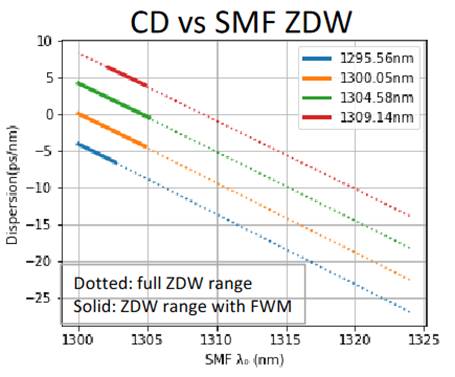
Slide#9 on rodes_3df_01b_221012 shows the relation of lambda zero with dispersion and FWM.
The FWM penalty will be negligible for each channel outside certain lambda0 range. The dotted sections of the lines in the graph below represent the ranges of lambda0 with negligible FWM. In general, FWM starts to be a possibility with fiber lambda0 ~1305nm or lower. You can see how at 9.5ps/nm and -28.4ps/nm you only need to worry about CD, and not about FWM.
I am sorry for the many questions raised in this email but I think it’s important to get clear answers in our attempt to create a robust and manufacturable 800G-LR4 specification and to remove any shred of doubt.
Thank you Peter for all these relevant questions. They are very important to build a robust spec. We hope we have satisfactorily answered all of them, and we will continue working with all Task Force members to refine the 800G-LR4 IMDD specifications together. We understand that we still have plenty of work ahead.
Regards,
Roberto
From: Peter Stassar <000017da312dfb6f-dmarc-request@xxxxxxxxxxxxxxxxx>
Sent: Wednesday, November 23, 2022 11:41 AM
To: STDS-802-3-B400G@xxxxxxxxxxxxxxxxx
Subject: [EXTERNAL]: Re: [802.3_B400G] Further questions for clarification
Hi Chris,
Thanks. Looking forward to the further information.
Happy Thanksgiving to you, our colleagues and their families.
Kind regards,
Peter
From: Chris Cole [mailto:chris@xxxxxxxxxxxxxxx]
Sent: Wednesday, November 23, 2022 7:38 PM
To: STDS-802-3-B400G@xxxxxxxxxxxxxxxxx
Subject: Re: [802.3_B400G] Further questions for clarification
Hello Peter,
These are all excellent questions and deserve detailed answers either on the reflector or in future presentations. Thank you very much for returning the discussion of optics alternatives back into the technical realm where it belongs for multiple next meeting cycles. If we focus on dBs instead of bananas, the optics track debate will again match the copper track in substance.
Happy Thanksgiving everyone
Chris
On Tue, Nov 22, 2022 at 6:43 AM Peter Stassar <000017da312dfb6f-dmarc-request@xxxxxxxxxxxxxxxxx> wrote:
Hi Roberto, and co-authors
Thanks again for your very detailed proposal contained in your presentation, https://www.ieee802.org/3/df/public/22_11/rodes_3df_01a_2211.pdf [ieee802.org]The updated version which you showed during the meeting last Wednesday is now also available on-line.
As you know I raised some questions to better understand the proposal. Unfortunately I wasn’t unable to fully understand the answers provided, probably due to the non-optimum audio conditions in the meeting room.
Therefore I will be raising them again in this email (also in view of the updated presentation).
The first question which I raised was related to the range between OMAouter min (for max TDECQ), being 4.4 dBm, and OMAouter max, being 5 dBm, and how that would work in manufacturing, considering that during the cu project there were requests to raise that difference for the 400GBASE-LR4-6 from 2.1 to 2.5 dB.
It was my understanding that you acknowledged that this range was tighter than desirable and that it would need to be considered if it would be possible to raise the OMAouter max to 5.5 dBm.
This however raises further questions:
· Is a range of 1.1 dB for OMAouter at max TDECQ sufficient for setting in manufacturing, considering that +/- 0.25 dB is generally seen as a ballpark testing/reproducibility accuracy? Or would you need to go more towards a range of 2 dB which seems to be a ballpark minimum range of in-force IEEE optical PMDs.
· Is a nominal Tx power of 5 dBm (OMAouter) achievable with current 200G PAM4 laser technology?
· Is a Receiver overload of 5.5 dBm achievable, considering that it would seem important to operate in all back-to-back configurations?
· Was is the impact on the FWM analysis by the raise in power by 0.5 dB?
One intermediate question is related to the proposal for “Difference in launch power between any two lanes” to be “3 dB” max.
Is this average launch power or OMA? In the in-force specifications for 400GBASE-FR4 and 400GBASE-LR4-6 it is in OMA.
Now back to my second question raised at last week’s meeting.
In your specification proposal on slide 6, you propose a max difference in launch power between any two lanes of 3 dB.
Shouldn’t we take that range into consideration for the analysis of FWM?
In October there was a presentation by your co-author Xiang Liu proposing to use a flat distribution of power per channel, whereas his first (and superseded) presentation assumed a range of 3 dB. Wouldn’t we need to use that range of 3 dB for the FWM analysis?
Now, having been able to further look into the proposals in your updated presentation, I have some further questions for clarification, especially around the assessment of FWM penalty.
· What are the precise assumptions used for this analysis looking at your slide 5 (and your October presentation https://www.ieee802.org/3/df/public/22_10/22_1012/rodes_3df_01b_221012.pdf [ieee802.org])?
o Are you indeed using a lambda zero Gaussian distribution between 1306 and 1322nm? Instead of a flat distribution?
o In your October presentation you mentioned “Uniform distribution of ZDW is unrealistic and it overestimates FWM probability”. How would the analysis turn out if we would use a less rigid approach like distribution between 1303 and 1322nm? Flat versus Gaussian. It would be helpful to understand if we are close to running off a cliff or not.
· Are you indeed using Gaussian distributions for Lambda Zero, AND, optical power as I seem to understand from your slide 5?
· Do I understand correctly that you are using an OMA distribution with a range of 1.5 dB instead of the 3 dB range you propose on slide 6?
Then on the combined TDECQ + FWM penalty.
· Are you indeed assuming that the combination never goes above 3.9 dB?
· So are you assuming that for the channels with TDECQ close to 3.9 dB the FWM penalty will be negligible?
· Considering that the highest CD penalty would seem to occur at the 1309.14 nm channel with 9.5 ps/nm, would you indeed expect the FWM penalty for that channel to be negligible? And similarly for the 1295.56nm channel with -28.4 ps/nm?
o How dependent is this assumption on the fiber lambda zero?
I am sorry for the many questions raised in this email but I think it’s important to get clear answers in our attempt to create a robust and manufacturable 800G-LR4 specification and to remove any shred of doubt.
Thanks in advance.
Kind regards,
Peter
To unsubscribe from the STDS-802-3-B400G list, click the following link: https://listserv.ieee.org/cgi-bin/wa?SUBED1=STDS-802-3-B400G&A=1 [listserv.ieee.org]
To unsubscribe from the STDS-802-3-B400G list, click the following link: https://listserv.ieee.org/cgi-bin/wa?SUBED1=STDS-802-3-B400G&A=1 [listserv.ieee.org]
To unsubscribe from the STDS-802-3-B400G list, click the following link: https://listserv.ieee.org/cgi-bin/wa?SUBED1=STDS-802-3-B400G&A=1 [listserv.ieee.org]
To unsubscribe from the STDS-802-3-B400G list, click the following link: https://listserv.ieee.org/cgi-bin/wa?SUBED1=STDS-802-3-B400G&A=1 [listserv.ieee.org]
To unsubscribe from the STDS-802-3-B400G list, click the following link: https://listserv.ieee.org/cgi-bin/wa?SUBED1=STDS-802-3-B400G&A=1 [listserv.ieee.org]
To unsubscribe from the STDS-802-3-B400G list, click the following link:
https://listserv.ieee.org/cgi-bin/wa?SUBED1=STDS-802-3-B400G&A=1
To unsubscribe from the STDS-802-3-B400G list, click the following link: https://listserv.ieee.org/cgi-bin/wa?SUBED1=STDS-802-3-B400G&A=1