Hi Morteza,
Thanks for the questions, please see my response inline.
Best,
Jason
发件人: Morteza
Mehrnoush [mailto:mmehrnoush@xxxxxxxx]
发送时间: 2022年11月2日 1:10
收件人: STDS-802-11-TGBE@xxxxxxxxxxxxxxxxx; Guoyuchen (Jason Yuchen Guo) <guoyuchen@xxxxxxxxxx>
主题: Re: Discussion for the contribution 11/22-1250r1 - ML SM PS mode
Hi Jason,
Thanks for sharing the simulation results. I have a few questions.
What is the traffic rate in UL/DL? How many traffic streams you have between the AP MLD and non-AP MLDs?
[Jason] We simulate DL only since this scheme is more for DL. The unit of the traffic rate is Mbps, sorry for missing that in the figure.
We consider one traffic stream between the AP MLD and each non-AP MLD.
Based on the Active Time for Scheme 2, it looks like the traffic load (total traffic rate over total phy rate) is low to medium. Do you have any result
when the traffic load is high?
[Jason] The figure illustrates the result for 1 AP MLD and 1 non-AP MLD, for more AP MLDs and non-AP MLDs, the results are similar regarding
the relative relationship of the three schemes.
What is the definition of the transmission time in your simulation? How is it different than the MAC layer latency (which includes queueing, channel access,
TX duration, etc)?
[Jason] transmission delay = t1-t0, where t0 is the time when the packet arrives in the queue, t1 is the time when the packet is successfully transmitted. It
is the same as the MAC layer latency as you mentioned.
Thanks,
Morteza
From: Guoyuchen (Jason Yuchen Guo) <000018696e95f088-dmarc-request@xxxxxxxxxxxxxxxxx>
Sent: Monday, October 31, 2022 9:26 PM
To: STDS-802-11-TGBE@xxxxxxxxxxxxxxxxx <STDS-802-11-TGBE@xxxxxxxxxxxxxxxxx>
Subject: [STDS-802-11-TGBE] Discussion for the contribution 11/22-1250r1 - ML SM PS mode
Dear TGbe members, I initiate this email thread to discuss the contribution 11/22-1250r1, which was presented in the MAC ad-hoc meeting this Monday. I received
several sets of comments during the call, and I’d like to resolve the comments
ZjQcmQRYFpfptBannerStart
This Message Is From an External Sender
ZjQcmQRYFpfptBannerEnd
Dear TGbe members,
I initiate this email thread to discuss the contribution 11/22-1250r1, which was presented in the MAC ad-hoc meeting this Monday.
I received several sets of comments during the call, and I’d like to resolve the comments here.
<Comment 1> Please clarify the relationship between the ML SM PS mode and the link level dynamic SM PS mode.
<Comment 2> Please also clarify that the non-AP MLD can only use one mode at a time among the ML SM PS mode, the EMLSR mode and the EMLMR mode.
I added a new paragraph to the new revision
11/22-1250r2 as below:
A non-AP MLD shall not operate in the MLSM power save mode if any of its affiliated STA is operating in the static SM power save mode or the dynamic SM power
save mode. A non-AP MLD shall not operate in the MLSM power save mode if it is operating in the EMLSR mode or the EMLMR mode.
<Comment 3> non-AP MLD can use other method to do the power save, e.g., cross-link power state indication
I did some system-level simulation to demonstrate the efficiency of the ML SM power save mode as illustrated below.
Simulation settings:
Traffic: DL ; AP MLD number: 1-2 ; non-AP MLD number: 1-4; Link number: 2 ; NSS per link: 1 ; Link 1 (primary) is 20MHz (assuming 2.4GHz band) ; Link 2 is 80MHz (assuming 5GHz band) ; Packet size: 1500 bytes
Simulation scheme 1 (ML AM PS mode):
Non-AP behavior: monitor on link 1 only. After receiving an initial frame (e.g., RTS), turn on link 2.
AP behavior: contend the channel on both link 1 and link 2, need to transmit an RTS on link 1 first, then transmit on link 2.
Simulation scheme 2 (independent access):
Assume two links are STR, each link can perform transmission independently.
Simulation scheme 3 (cross-link power state indication):
AP MLD only contends on link 1 and transmits to the non-AP MLD, the non-AP MLD will indicate to the AP MLD whether it turns on the other link (probability is p). In the figures below, the line marked as “COMP 1.0” corresponds to this scheme
3 with p=1.0, the line marked as “COMP 0.3” corresponds to this scheme 3, with p=0.3, and the line marked as “COMP 0.6” corresponds to this scheme 3, with p=0.6.
Simulation output:
Metric 1: transmission delay
Metric 2: the amount of time that the radio is active (normalized to scheme 2. Note that in scheme 2, two links are always active.)
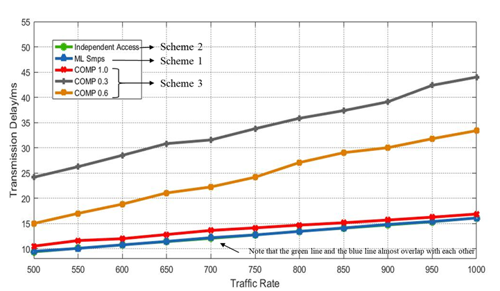
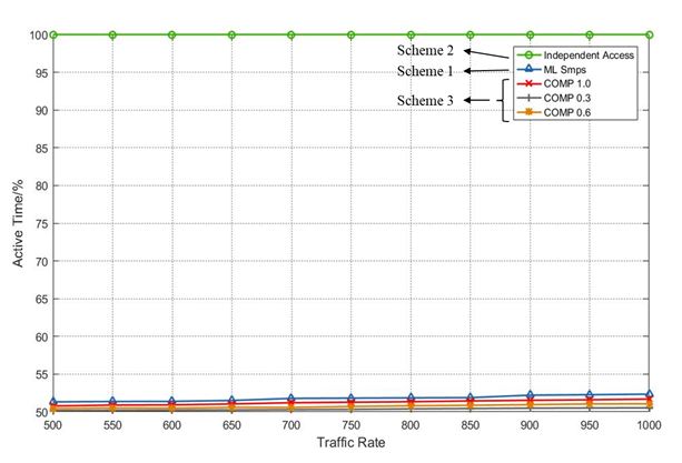
Analysis:
Scheme 2 (independent access) has the lowest transmission delay, but the power consumption is highest.
Scheme 3 (cross-link power state indication) consumes similar power as the ML SM PS mode, but the transmission delay is higher.
Scheme 1 (ML SM PS mode) balances the transmission delay and power consumption. It reduces the power consumption to a relatively low level, and does not increase the transmission delay.
<Comment 4> the scheme does not save power. Comparatively, other modes (e.g., EMLSR mode) saves power.
As shown in the simulation result above, this scheme really saves power. Moreover, it balances the power consumption with the transmission delay.
The ML SM PS mode does not prevent the non-AP MLD from using the other modes, the non-AP MLD can choose to use any of these modes for its own need.
Each mode has its pros and cons, e.g., the EMLSR mode works well for single radio non-AP MLD, and the ML SM PS mode only requires one RF chain to be active for most of the time, which is good for low power consumption.
Best,
Jason Yuchen Guo
To unsubscribe from the STDS-802-11-TGBE list, click the following link:
https://listserv.ieee.org/cgi-bin/wa?SUBED1=STDS-802-11-TGBE&A=1
To unsubscribe from the STDS-802-11-TGBE list, click the following link: https://listserv.ieee.org/cgi-bin/wa?SUBED1=STDS-802-11-TGBE&A=1