Hi Wei,
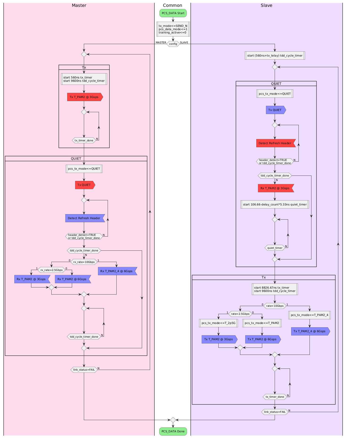
Below is on my attempt to generate an Action Diagram for the New-TDD data mode. I struggled with understanding how the synchronization between Master and Slave should be done in an interoperable manner. I
would greatly appreciate your feedback on my diagram below.
One of the things that was not clear to me from your baseline text proposal was when the Master should start transmitting again. Since the TDD cycle duration is 9600ns, I introduced tdd_cycle_timer in my diagram
to control the Master transmit intervals. Is this in line with what was intended, or is there a better way to determine the interval between Master transmit bursts?
If I understand the text correctly, the Slave will start transmitting 106.66ns-delay_cout*5.33ns after the end of the received transmission from the Master. But what happens if the Slave does not lock on to
the Refresh Header signal from the Master? In this case the end of received transmission from the Master may not be well defined. I tried to work around this by using tdd_cycle_timer (again, this timer is not defined in your text) timeout to transition to
transmit mode if no Refresh Header is detected. Do you think that this approach results in an interoperable implementation, or is there a better way to deal with this ambiguity?
According to Clause 200.6.2.4.6, the delay count can take values from 0 to 31. This means that maximum delay adjustment is about 165ns (31*5.33ns), which is more than the 106.66ns IBG duration. Would it make
sense to limit the range of the delay_count value to correspond to the IBG duration? Or better still to increase the IBG to 165ns, to allow for operation over longer cables.
If I understand the New-TDD state diagram correctly, both Master and Slave go directly into data mode, without waiting for block_lock after switching to the data mode framing. Did I understand this correctly?
Does this mean that data can start flowing over the local XGMII interface before the remote receiver is ready to receive it?
Ragnar
From: Ragnar Jonsson
Sent: Tuesday, July 15, 2025 11:07 AM
To: Wei Lou <wei.lou@xxxxxxxxxxxx>; STDS-802-3-ISAAC@xxxxxxxxxxxxxxxxx
Subject: RE: [802.3_ISAAC] [EXTERNAL] Re: [802.3_ISAAC] Question on Baseline Text Proposal for TDD Based 802.3dm PHY
Hi Wei,
Thanks once again for your prompt response to my questions.
Regarding the comment about the PHYC state diagram having sufficient information, I am not sure that this is the case. The current New-TDD baseline text was provided “fully formed” to the task force without
any explanation of how the solution was derived. My following questions related to the SILENT1 state should demonstrate this.
I have now implemented a simulation of the New-TDD Control State Diagram, and I have several questions related to the SILENT1 state:
- Why is the SILENT1 state needed, and does it serve any purpose for the receiver on the Master side?
- The slave will exit the SILENT1 state as soon as loc_rcvr_state1 is OK, without any min_wait_timer, so theoretically the Slave could fall directly through
the SILENT1 state. Would this be a potential interoperability problem for the Master?
- The SILENT1 state has config_timer that is started when entering the SILENT1 state, and if this timer expires before exiting the SILENT1 state, the state
will transition to the SILENT0 state. As far as I can tell there is no way for the Master to know if the Slave is still in the SILENT1 state or if it has transitioned to the SILENT0 state. The Master is now transmitting SEND_TA, but the Slave is expecting
SENS_TS and will probably be stuck in the SILENT0 state. The startup sequence is now dead-locked as far as I can tell. Am I missing something?
Regarding the dead-lock in case 3 above, what happened in my simulation was the following:
- The Master is stuck in the TRAINING1 state until the link_fail_inhibit_timer will expire
- The Master transitions to the DISABLE_TRASMIT state and starts all over again and stops in the TRANINING0 state
- The Slave stays stuck in the SILENT0 state, even after its link_fail_inhibit_timer has expired, until it declares loc_rcvr_status is OK
- The Slave declears loc_rcvr_status is OK and transitions to the TRAINING0 state, but it’s link_fail_inhibit_timer has expired so it transitions straight
into DISABLE_TRANSMIT and starts over again
What happens next is implementation specific. If the Slave started transmitting before it exited the TRAINING0 state it might confuse the Master, but this is again implementation dependent. Are you seeing
similar things in your simulations?
Ragnar
From: Wei Lou <000047a3c8c56bbe-dmarc-request@xxxxxxxxxxxxxxxxx>
Sent: Sunday, July 13, 2025 6:10 PM
To: STDS-802-3-ISAAC@xxxxxxxxxxxxxxxxx
Subject: Re: [802.3_ISAAC] [EXTERNAL] Re: [802.3_ISAAC] Question on Baseline Text Proposal for TDD Based 802.3dm PHY
Hi, Ragnar, Regarding loc_rcvr_status, statements b) and c) are both similarly defined in IEEE 802. 3ch.
I agree with you that statement c) indicates that frame synchronization is required before loc_rcvr_status = OK. Please also note that pcs_status
ZjQcmQRYFpfptBannerStart
|
ZjQcmQRYFpfptBannerEnd
Hi, Ragnar,
Regarding loc_rcvr_status, statements b) and c) are both similarly defined in IEEE 802.3ch. I agree with you that statement c) indicates that frame synchronization is required before loc_rcvr_status = OK. Please also note that pcs_status and scr_status are used in data mode and training mode, respectively. I believe statement c) provides a fairly clear definition for loc_rcvr_status = OK.
As for statement b), the full sentence from the TDD text proposal reads:
“When loc_rcvr_status indicates OK, then the PCS Synchronization process accepts data-units via the PMA_UNITDATA.indication primitive. It attains frame and block synchronization based on the PMA training frames and conveys received blocks to the PCS Receive process when PHY control is in PCS_DATA state.”
In addition to the original sentence from IEEE 802.3ch, we added the clause “when PHY control is in PCS_DATA state” in our proposal for clarity—because block synchronization, in our view, only applies during data mode.
So, the proposal we’re presenting is not introducing anything fundamentally new; it’s consistent with both 802.3bp and 802.3ch.
Finally, since receiver design is implementation-dependent, I won’t comment on your specific state diagram. We believe our PHYC state diagram text proposal is sufficient as currently written.
Thank you!
Wei
________________________________________________________________________
To unsubscribe from the STDS-802-3-ISAAC list, click the following link: https://urldefense.proofpoint.com/v2/url?u=https-3A__listserv.ieee.org_cgi-2Dbin_wa-3FSUBED1-3DSTDS-2D802-2D3-2DISAAC-26A-3D1&d=DwIFaQ&c=nKjWec2b6R0mOyPaz7xtfQ&r=hiHgBSUj2X0k3TORVxe0NCZAlJs6SEDHhwLDz5m9MbY&m=3dDl1ZUF-uXT7J1ynjH5Se8zuoPPO7cGvSbVXqoWPLElWOzfFGYn1sLSglvu5ldL&s=0G8QbwmNGssGaDoI89omCePrZcvsmsuhhB2-TfJ9wTY&e=
To unsubscribe from the STDS-802-3-ISAAC list, click the following link: https://listserv.ieee.org/cgi-bin/wa?SUBED1=STDS-802-3-ISAAC&A=1