Hi Rui,
Thanks for your comments and please find my answers inline as follows.
Best wishes,
Rui Du
发件人: Rui Yang [mailto:Rui.Yang@xxxxxxxxxxxxxxxx]
发送时间: 2022年1月13日
22:39
收件人: STDS-802-11-TGBF@xxxxxxxxxxxxxxxxx
主题: Re: [STDS-802-11-TGBF] Discussion for 20/1288 (TCIR) and the motion
Hi Rui Du,
Thank you for reaching out for comments. I apologize for missing your comment collection before.
Regarding the motion (#49) you proposed, I have a few concerns:
1.
It is not clear to me why the frequency domain CSI is not sufficient for sensing? If the concern is about feedback overhead, it would be better to consider additional reduction
based on the existing compressed CSI feedback. To generate the time domain CSI, the sensing receiver may need additional processing power, which would not be desirable.
[Rui Du] I am not very sure if the ‘compressed CSI feedback’ you mentioned is the
compressed beamforming matrix(the precoding matrix) in the main stream of 802.11 or not. But if you mean
compressed beamforming matrix here, the conclusion from TGbf is that
it cannot
be adopted for WLAN sensing directly, and that is the main reason why TGbf want to reuse the CSI matrix as a feedback type. If you have some ideas about how can we use compressed beamforming matrix in WLAN sensing,
I think the group will be very happy to discuss it.
So, in this email, I am only focus on the evaluation of
frequency domain CSI (CSI matrix) and
CIR for sensing, and explain the reasons why we need the CIR.
It is true that the feedback overhead of frequency domain CSI can be reduced with greater grouping factor Ng, but
(T)CIR could provide more advantages than overhead reduction! Here is one example figure (assuming 5 subcarriers) describes the approach of frequency
domain CSI grouping.
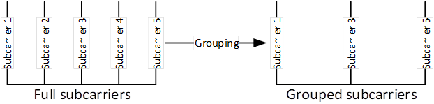
Figure 1
[1]
It should be noted that
full subcarriers is better than grouped subcarriers for sensing
theoretically. This can be easily understood if we think about the CRLB (Cramér-Rao Lower Bound), which is the theoretical bound describes the lower bound of MSE in the parameter estimation. The CRLB of delay can be calculated
with the following equation.
![]()
For simplicity, we are discussing a single antenna case and the
![]() in the above equation is the SNR level at the receiving antenna.
in the above equation is the SNR level at the receiving antenna.
![]() is the root mean square bandwidth of the signal used for sensing and can be calculated with equation
is the root mean square bandwidth of the signal used for sensing and can be calculated with equation
![]() . It is easy for us to know that the
. It is easy for us to know that the
![]() of full subcarriers is greater than
of full subcarriers is greater than ![]() of grouped subcarriers, which means the CRLB of full subcarrier is lower than that of the grouped subcarriers. That is the
theoretical
reason why full subcarriers is better than grouped subcarrier in sensing.
of grouped subcarriers, which means the CRLB of full subcarrier is lower than that of the grouped subcarriers. That is the
theoretical
reason why full subcarriers is better than grouped subcarrier in sensing.
[2]
Based on the feedback procedure of frequency domain CSI, the full subcarrier CSI is estimated and obtained at sensing receiver. Then the full subcarrier CSI will be grouped
and fed back to sensing transmitter, which means the sensing transmitter can perform sensing
only with the grouped subcarriers CSI.
In the simulation of DCN 21/1288, the (T)CIR we presented is generated with full subcarrier rather than grouped subcarrier.
The result indicates that the sidelobe generated with full subcarrier is lower than the sidelobe generated with grouped subcarrier. The sidelobe level is very important in sensing
for further detection and parameter estimation. One simulation result from 21/1288
is pasted here as figure 2.
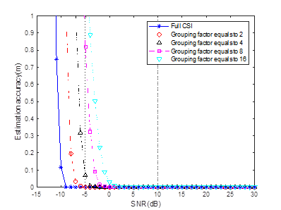
Figure 2
In figure 2, the x-axis is the SNR level and y-axis is the estimation accuracy. The simulation
results show that the estimation accuracy
improves with the SNR increases. More important is that, the results clearly indicate that the
sensing performance decreases with grouping number Ng increases. The
simulation results are consistent with the theoretical analysis we mentioned above.
[3]
It is the
feedback overhead reduction. The feedback overhead of TICR is much smaller than the Ng can be used for now(Ng can be further increase for overhead reduction but the performance will
further reduced, as the analysis listed above).
Based on the advantages described above on, TCIR could achieve
better performance (and lower overhead) if the target is located in the feedback subset of the CIR. The problem that how the
subset of CIR should be selected is explained in the answer for Question 3.
2.
The first sub-bullet of the motion text (“Calculating the CIR (time domain) from frequency domain CSI through IDFT(usually, IFFT)” ) appears an implementation. Is your
intention to mandate this operation at sensing receivers?
[Rui Du] I am
not preventing any other methods or techniques
that can be used to generate CIR. If you have any potential suggestion, we could discuss it.
Based on my understanding,
FFT/IFFT is definitely a good choice based on two reasons.
[1]
FFT/IFFT is widely adopted in the wireless communication already due to its low complexity and some other advantages, it is a good choice that we can
reuse it.
[2]
FFT/IFFT is an linear integral transformation. The adoption of FFT/IFFT usually
won’t add any distortion to the signal and remain the information that is needed for further sensing processing. For example, angle information
can be estimated based on the multiple CIRs (generated from frequency domain CSI by IFFT) from multiple antennas.
3.
In the second sub-bullet of the motion, you have “complex samples corresponding to the range of interest of the entire CIR”. I am not sure how the “entire CIR” is defined
and if it can be defined consistently among different sensing receivers. In addition, from your early contributions, it clears to me that this set of complex numbers (i.e., PDP?) may vary a lot depending on the algorithm at the sensing receiver (e.g., grouping
size and timing relationship among those numbers). So, the question is how you can guarantee the consistency of the measurements from different sensing receivers.
[Rui Du] In
the contribution, the
entire CIR is
defined as the
output of IFFT of the full subcarrier CSI.
And as we stated in the contribution, CIR may
be affected by the synchronization offset. An example is
shown in figure 3, solid line is the amplitude of the 1st CIR and dash line is the amplitude of the 2nd CIR. The amplitude of the 1st CIR and 2nd CIR may be different because the time
synchronization is performed per PPDU. The important thing is that the relative delay Δt between the 1st peak and 2nd peak remain
constant in different CIRs in a sensing device within coherent time. Physically,
Δt represents the
propagation difference between LOS and reflection path (R1+R2) as figure 4 shows. So, with some ideas borrowed from 60GHz, the consistency of the measurements
((T)CIRs) from single device can be achieved by selecting the subset with a reference point (e.g. the tap with largest amplitude). That means, no matter how CIRs is affected by the synchronization offset,
the subset can be chosen around the tap with largest magnitude, and the
consistency can be achieved.
I am a little bit confused with the ‘consistency of measurements from different
receivers’ ? Can you explain
why we need the consistency from different receivers
? So I can do further clarifications.
If you mean ‘how can we fuse the results from different sensing receivers ?’
The answer is that this is another complicated problem which is not related to what I proposed.
But, please bear in mind that, If we have
multiple devices in the sensing, the
consistency of measurements per device can be achieved
by the method we mentioned above. The CIRs measured at
multiple receivers are different due to the different positions of receivers (e.g.
assuming on transmitter and multiple receiver in figure 5), because they are
coming from different
sensing links. The important thing is to make the measurement per device consistent.
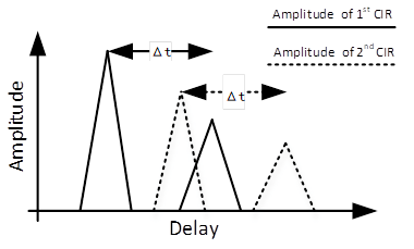
Figure 3
Figure
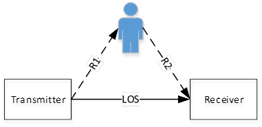
Figure 4
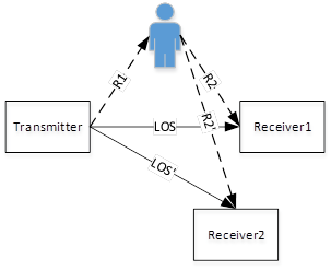
Figure 5
In general, I believe we should not ask sensing receivers, which need to feedback sensing measurement results, to process CSI for a measurement
that we cannot ensure the consistency of its meaning and reference value over time and among different sensing devices.
[Rui Du] Based on my understanding, it is
easy for the measurements to achieve
consistency for each individual device
with some selection rules mentioned above. And what I proposed here is
trying to maximally utilize the signal for sensing with a very
simple
processing.
[Rui Du] Please let me know if you have any further comments or questions.
Best regards,
Ray
From: durui (D) <000017788cb650b9-dmarc-request@xxxxxxxxxxxxxxxxx>
Sent: Tuesday, January 11, 2022 10:44 PM
To: STDS-802-11-TGBF@xxxxxxxxxxxxxxxxx
Subject: [STDS-802-11-TGBF] Discussion for 20/1288 (TCIR) and the motion
Dear all,
I am sending this email to initiate a discussion on the contribution 21/1288 Truncated Power Delay Profile(Truncated Channel Impulse Response) - follow up and motion 49 I ran
yesterday.
Actually, I already tried to collect as much opinions as possible from the group member before the motion, and I thought I’ve discussed thoroughly with the group members who
feedback their concerns or questions. I was surprised with the motion results.
Hence, I would like to discuss if there is any further concerns. Please feel free to let me know (by 11bf reflector or private email) your thoughts and any suggestions for the
contribution and the motion.
Best wishes,
Rui Du
To unsubscribe from the STDS-802-11-TGBF list, click the following link:
https://listserv.ieee.org/cgi-bin/wa?SUBED1=STDS-802-11-TGBF&A=1
To unsubscribe from the STDS-802-11-TGBF list, click the following link:
https://listserv.ieee.org/cgi-bin/wa?SUBED1=STDS-802-11-TGBF&A=1
To unsubscribe from the STDS-802-11-TGBF list, click the following link: https://listserv.ieee.org/cgi-bin/wa?SUBED1=STDS-802-11-TGBF&A=1