Hi Rui,
Thanks for the detailed response.
“[1] As I stated in previous contribution and email, TCIR has the same sensing performance with full CSI(Ng=1) if TCIR can be properly selected, because the proposed TCIR is generated with full CSI. So, in WLAN sensing, if frequency domain CSI is always fed back with Ng=1, we don’t need TCIR and CIR can be calculated by the application! But, will we always using Ng=1 in 11bf ?”
The Ng used for frequency domain feedback is debatable but I’m struggling to see a need for any Ng<4.
“Another important thing is that, no matter what bandwidth are adopted here, the performance gap between TCIR and grouped CSI still exists. The reason is that we are evaluating the sensing performance based on subcarriers without grouping(Ng=1) and with grouping (Ng>1) for certain bandwidth.
[1] For example, for 20MHz bandwidth, we are evaluating the sensing performance based on TICR generated with 242 subcarriers and sensing performance based on subcarrier with Ng=16.
[2] For 80 MHz bandwidth, more subcarriers can be used for sensing. But now we are evaluating the sensing performance based on TICR generated with 996 subcarriers and sensing performance based on subcarriers with Ng =16.”
Truncation in time is a form of smoothing – when you compare feedback using TCIR of 80MHz with truncation to 1024/4 or 1024/16 samples to frequency domain using Ng=4 or Ng=16, did you smooth the frequency domain first? If you didn’t then you compared apples to oranges.
Now granted forcing a STA to do TCIR is essentially forcing some form of smoothing but we typically don’t force smoothing for feedback.
Thanks,
Ron
From: durui (D) <000017788cb650b9-dmarc-request@xxxxxxxxxxxxxxxxx>
Sent: Sunday, January 23, 2022 11:43 PM
To: STDS-802-11-TGBF@xxxxxxxxxxxxxxxxx
Subject: [STDS-802-11-TGBF] 答复: [STDS-802-11-TGBF] 答复: [STDS-802-11-TGBF] 答复: Discussion for 20/1288 (TCIR) and the motion
Hi Ron,
Thanks for your email and please find my replies inline as follows.
Best wishes,
Rui Du
发件人: Ron Porat [mailto:ron.porat@xxxxxxxxxxxx]
发送时间: 2022年1月22日 3:25
收件人: durui (D) <ray.du@xxxxxxxxxx>; STDS-802-11-TGBF@xxxxxxxxxxxxxxxxx
主题: RE: [STDS-802-11-TGBF] 答复: [STDS-802-11-TGBF] 答复: Discussion for 20/1288 (TCIR) and the motion
Hi Rui,
Thanks very much for the quick answers. At this point I don’t recall the exact discussions in 11ac MU-MIMO feedback.
[Rui Du] OK, if you have any further information about this MU-MIMO case, we can further discuss that.
The main reasons to apply TCIR in sensing are:
[1] The transformation is applied on full subcarriers and maximally utilizing the information we have at receiver.
[2] For a 4x frequency domain CSI with subcarrier spacing ![]() , if we transform frequency domain CSI to time CIR, the maximum unambiguity range (calculated by
, if we transform frequency domain CSI to time CIR, the maximum unambiguity range (calculated by ![]() ) could achieve more than 3000 meters and is heavily redundant for WLAN sensing (usually <20 meters ).
) could achieve more than 3000 meters and is heavily redundant for WLAN sensing (usually <20 meters ).
They are the two main reasons why we transform the frequency domain CSI to CIR first and truncate it in time domain.
Based on my understanding, in a MU MIMO case, the CSI is used for the precoding in MIMO transmission. The accurate recovering of CSI from CIR may be is needed (btw, there is some other contributions discussing the fidelity of the CIR (21/1635) in 11bf).
In sensing, what we want is to extract some features of the intended target in the environment, only the information from target is desired, and we don’t need to recover the entire frequency domain CSI. As the description above, some information in CSI is redundant for sensing, even the CSI matrix with Ng=1 is fed back to application, the redundant information will also be ignored by the application (more information can be found in the answer for question 3).
I generally think that an SNR range>10dB is more applicable to us in reality and negative SNR as shown in the plots below are of no interest. Same for 20MHz BW, to the extent that it makes a difference it’s better to see results for 160MHz BW or at least 80MHz, at the least you will get more feedback tones even with Ng=16 for 160MHz BW.
[Rui Du] First of all, I think for communication, it is ok to consider the cases that SNR range >10dB. But for sensing, this SNR range is not comprehensive, sensing need to consider a larger SNR range.
The main reason is that sensing is a two way transmission (![]() ) and communication is a one way transmission(
) and communication is a one way transmission(![]() ).
).
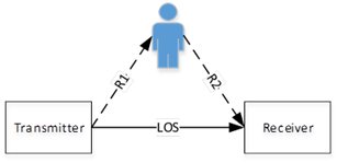
Figure 1
So, the ratio of ![]() and
and ![]() at the same device can be derived as the follow equation.
at the same device can be derived as the follow equation.
![]()
where ![]() is the distance from transmitter to receiver,
is the distance from transmitter to receiver, ![]() is the distance from target to receiver,
is the distance from target to receiver, ![]() is the distance of range, and
is the distance of range, and ![]() is the Radar Cross Section of human.
is the Radar Cross Section of human.
To make it simple, let’s assume a case in which ![]() ,
,![]() ,
,![]() , and
, and ![]() (already quite a large RCS value to represent human being). We can find that
(already quite a large RCS value to represent human being). We can find that ![]() , which mean the SNR of the intended target could be much smaller than that of LOS (and this happens a lot actually).
, which mean the SNR of the intended target could be much smaller than that of LOS (and this happens a lot actually).
Although some integration method could be adopted to improve the SNR, the number of CSI needed is very large. For example, we can consider the non-coherent integration (based on my understanding, it is very hard to adopted coherent integration at sub 7GHz) whose gain is ![]() ,
, ![]() is the number of CSI used for integration. If we want to achieve
is the number of CSI used for integration. If we want to achieve ![]() gain, more than 3000 CSI is needed !
gain, more than 3000 CSI is needed !
So, we can not only consider a SNR range > 10 dB for sensing. But I do agree that SNR range shouldn’t be too low for consideration, may be >0 is a good region. SNR>0 is also the typical SNR range that a BPSK/QPSK PPDU (bandwidth ![]() 80MHz) can be decoded.
80MHz) can be decoded.
Secondly, sensing performance will get improved with the bandwidth increases. Figure 2 is the simulation based on 4x 80MHz bandwidth PPDU. To make it more realistic, a target which is 17.5 dB smaller than LOS is simulated here.
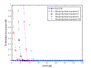
Figure 2
It is true that the sensing performance increases with the bandwidth increases. But, the performance gap between TCIR(Full CSI) and group CSI still exists. And please note that this is just an example and ![]() is used, for some other use cases(e.g. hand gesture recognition, breath detection, etc.),
is used, for some other use cases(e.g. hand gesture recognition, breath detection, etc.), ![]() could be even greater. In these cases, the SNR level needed to achieve good sensing performance is even greater.
could be even greater. In these cases, the SNR level needed to achieve good sensing performance is even greater.
Another important thing is that, no matter what bandwidth are adopted here, the performance gap between TCIR and grouped CSI still exists. The reason is that we are evaluating the sensing performance based on subcarriers without grouping(Ng=1) and with grouping (Ng>1) for certain bandwidth.
[1] For example, for 20MHz bandwidth, we are evaluating the sensing performance based on TICR generated with 242 subcarriers and sensing performance based on subcarrier with Ng=16.
[2] For 80 MHz bandwidth, more subcarriers can be used for sensing. But now we are evaluating the sensing performance based on TICR generated with 996 subcarriers and sensing performance based on subcarriers with Ng =16.
In addition with frequency domain feedback the sensing application can calculate time domain if it so desires.
[Rui Du] Exactly, the application definitely can do that !
Actually, the first and most fundamental step to estimate the range/delay by the application is to transform the frequency domain CSI to CIR and do the range/delay estimation of intended targets. The application will also truncate (or ignore) the CIR taps out of the range of interest to reduce the following processing computation complexity (e.g. doppler estimation, angle estimation, CFAR, …). But please note that, at application, the transformation only can be applied on grouped CSI (if the CSI is grouped in the feedback).
So, what I am proposing here is to apply the exactly same simple steps (i.e. transformation and truncation) at the device which generate CSI feedback to (1) fully utilize the full subcarrier CSI information and (2) reduce feedback overhead.
[1] As I stated in previous contribution and email, TCIR has the same sensing performance with full CSI(Ng=1) if TCIR can be properly selected, because the proposed TCIR is generated with full CSI. So, in WLAN sensing, if frequency domain CSI is always fed back with Ng=1, we don’t need TCIR and CIR can be calculated by the application! But, will we always using Ng=1 in 11bf ?
[2] Also, what I stated is TCIR could achieve better sensing performance than grouped CSI when they have same feedback overhead, and the feedback overhead of TCIR could be further reduced according to the applications.
Also, I’m not following why range estimation accuracy is the metric you chose for a sensing scheme that looks at channel variation.
[Rui Du] First of all, WLAN sensing is much more than just focus on channel variation.
[1] Channel variation is the simplest way to use CSI in WLAN sensing, it could work in some simple applications like present detection. But even for the present detection, channel variation only could provide ‘coarse results’ and more information is needed as well. For example, it is able to know that the channel is varying due to some ‘potential moving targets’ with channel variation. But without any other information, how can we know the target is located in this room or in a neighboring room ?
[2] In 11bf use case document, localization or tracking is needed in many use cases(e.g. home application control, store sensing, …). To realize this kind of use cases, further signal processing based on CSI and parameter estimation are definitely needed rather than just use the channel variation.
In summary, to fulfill different applications described in WLAN sensing, channel variation is not enough. Btw, I also would like to mention that the TCIR also maintain the trend of channel variation with FFT/IFFT (some simple simulation can be found in my previous contribution).
When we want to do more than channel variation, no matter localization or recognition, the first and most fundamental step is to ‘measure’ the target. The estimation accuracy usually is used to evaluate the performance when you measure target. Based on the measured information, you could realize some applications with further complicated signal processing techniques (e.g. Kalman filter for tracking and pattern recognition for recognition). So, estimation accuracy is chosen to evaluate the performance of the most fundamental step in WLAN sensing. And I think it is nature that good(accurate) fundamental measurements provide higher possibilities to achieve better performance in following sensing processing.
The reason why I chose range estimation accuracy rather than others (e.g. angle estimation accuracy or Doppler estimation accuracy) is described as follows.
As we all know, the range/delay information is projected along multiple subcarriers. What we are discussing now is how to compress the CSI along subcarriers which definitely affects the performance of range/delay estimation.
Also, if feedback overhead is a concern then sending an NDP is very efficient.
[Rui Du] I think this question has been discussed in 11bf previously, and the conclusion from the group is that sending a NDP cannot work for all scenarios in 11bf. Sending a NDP is a potential solution that may be adopted in some cases (let’s call it implicit feedback). But there are still some cases in 11bf that need explicit feedback, like:
[1] SBP case: In this case, STA is a sensing initiator and would ask AP to schedule sensing with multiple STAs. AP could conduct sensing with other STAs implicitly or explicitly. When sensing measurement is finished, AP need to feedback all the sensing results to the initiator STA (only can be done explicitly).
[2] In a MU cases, the channel or target can be measured from different aspect angles simultaneously. E.g. AP is transmitting a NDP and multiple STAs can receive the NDP and sense the target simultaneously. If implicit feedback is needed, to avoid the interference among different users, the NDP from multiple STAs need to be transmitted sequentially, which means the measurement is not conducted simultaneously.
[3] The asymmetry of DL measurement and UL measurement may make both information needed in sensing.
For this question, I only listed some ideas based on my personal understanding. And I think there will be more reasons why explicit feedback is needed in 11bf.
Thanks,
Ron
From: durui (D) <000017788cb650b9-dmarc-request@xxxxxxxxxxxxxxxxx>
Sent: Friday, January 21, 2022 3:49 AM
To: STDS-802-11-TGBF@xxxxxxxxxxxxxxxxx
Subject: [STDS-802-11-TGBF] 答复: [STDS-802-11-TGBF] 答复: Discussion for 20/1288 (TCIR) and the motion
Hi Ron,
Thanks for your email and please find my answers inline as follows.
We can have an online discussion if needed.
Best wishes,
Rui Du
发件人: Ron Porat [mailto:ron.porat@xxxxxxxxxxxx]
发送时间: 2022年1月21日 2:32
收件人: durui (D) <ray.du@xxxxxxxxxx>; STDS-802-11-TGBF@xxxxxxxxxxxxxxxxx
主题: RE: [STDS-802-11-TGBF] 答复: Discussion for 20/1288 (TCIR) and the motion
Hi Rui Du,
Can you compare TCIR to decimated frequency domain with the same total number of complex samples fed back?
[Rui Du] Attached please find the simulation results for the sensing performance of two different targets (a strong target and a weak target).
In the simulation, the legend ‘Full CSI’ represent TCIR and has the same number of complex samples with the legend ‘grouping factor equals to 16’(which represent Ng-16 is adopted during the grouping).
Please note that the simulation is just an example and the feedback size of TCIR can be further reduced according to the applications. For example, only 1 tap (the tap with largest magnitude) is used in the experimental validation for the finger tracking (the results can be find in DCN 0660/1288).
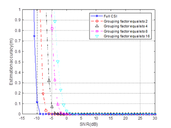
In the simulation the x-axis is SNR and y-axis is the range estimation accuracy (defined as the root mean square error between the estimated range and ground truth). Both results (sensing for strong target and weak target) indicate that the estimation accuracy based on TICR (legend with ‘full CSI’) is better than the sensing performance based on same numbers frequency CSI (legend with ‘grouping factor equals to 16’).
Also, why would the Rx work harder to generate TCIR if frequency domain is good enough? FYI already in 11ac (e.g 1131) time domain was discussed as channel feedback but was not accepted.
[Rui Du] This is a very good question and I think we need to discuss how can we define ‘good enough’.
First of all, the simulations have shown that the sensing performance of TCIR is better than that of grouped CSI. This also can be explained by the CRLB I mentioned in previous email. Experimental validation of TCIR for finger tracking also has been presented in my previous contributions. So, based on the above mentioned, I personally think that TCIR could achieve better sensing performance than grouped CSI.
Maybe another relevant question here is ‘if frequency domain CSI is good enough already’ ?
To be honest, I am not sure at this stage. In WLAN sensing, the most important information we want is the feature(s) of intended targets in a given environment. In different applications, the target could be a human being , a pet or even a hand (i.e. hand gesture recognition). So the signal reflected from the target could be very small and also much smaller than LOS signal (this is quite different with communication which mainly relies on the LOS signal in most cases). So, if we want to sense a unknown target (which may have very low SNR), definitely it is good to adopt a method that has ‘better performance’ rather than a method has ‘good performance’.
Also, many WLAN sensing academic papers has been published based on the CSI estimated at the receiver. To achieve better performance, the researchers always would like to use all the subcarriers rather than part of the subcarriers.
Thanks for your information. But I think the advantages of TCIR in sensing is different with that in communication. If possible, could you please share me more information about why it was not accepted in communication ?
Regards,
Ron
From: durui (D) <000017788cb650b9-dmarc-request@xxxxxxxxxxxxxxxxx>
Sent: Thursday, January 20, 2022 12:35 AM
To: STDS-802-11-TGBF@xxxxxxxxxxxxxxxxx
Subject: [STDS-802-11-TGBF] 答复: Discussion for 20/1288 (TCIR) and the motion
Hi Rui,
Sure, please take your time and also please find my answers inline as follows.
Best wishes,
Rui Du
发件人: Rui Yang [mailto:Rui.Yang@xxxxxxxxxxxxxxxx]
发送时间: 2022年1月19日 7:44
收件人: durui (D) <ray.du@xxxxxxxxxx>
抄送: STDS-802-11-TGBF@xxxxxxxxxxxxxxxxx
主题: RE: Discussion for 20/1288 (TCIR) and the motion
Dear Rui Du,
Thank you for your long responding email. If you don’t mind, I will try to address your comments/questions in a few days.
Meantime, may I ask if the result with “Full CSI” in Figure 2 corresponds to the full PDP or full CIR without truncation?
[Rui Du] The legend ‘Full CSI’ in the simulation in DCN 1288 represents truncated CIR (TCIR). In the simulation, two targets are located at 30m and 120m, respectively. The feedback size of TCIR ![]() , corresponding to the range of interest
, corresponding to the range of interest ![]() .
.
Please note that the parameter adopted in the simulation is just an example. According to the 11bf use case document, the maximum range for WLAN sensing is 20 meters (i.e. store sensing). This means the feedback size of TCIR can be further reduced.
Do you have the results with different truncation length (different CIR feedback size)? Thanks.
[Rui Du] If the TCIR of can be selected/truncated properly from the ‘full CIR’, the increase of TCIR feedback size will not affect the sensing performance.
This is mainly because the sidelobe is affected by the number of subcarriers adopted during the transformation from frequency domain CSI to time domain CIR. Since all the subcarriers are used by the IFFT to generate the ‘full CIR’, the ‘full CIR’ has low sidelobe levels, which will improve the sensing performance(as the simulations indicate). The only problem is that how the ‘full CIR’ can be truncated properly.
To select/truncate the TCIR properly, two criteria shall be met(as we described in the answer for Q3 in last email).
[1] The index or position of the TCIR shall be selected properly. This can be solved by a good reference tap(e.g. the tap with largest amplitude).
[2] The size of the TCIR shall be designed properly. As figure 3 in last email shows, the delay difference Δt between the largest magnitude tap (reference tap) and the following tap represent the propagation delay difference between LOS path and reflected path. So, in different applications, the size of the TICR is decided by the range of interest in each application (the calculation method is also provided in my previous contribution).
For example, the range of interest can be set to 5 meters(or a little bit longer) if the information within 5 meters is need. The most important thing is that the subset corresponding to 5 meters should be selected properly(as the criteria mentioned above), and any information beyond 5 meters is redundant in this case. If you want more information, you could adjust the range of interest according to your application.
In summary, if the index/position of the TCIR is selected properly and the feedback size is enough to cover the range of interest, the increase of TCIR feedback size will not affect the sensing performance.
Please let me know if you have any further questions or comments.
Best regards,
Ray
From: durui (D) <000017788cb650b9-dmarc-request@xxxxxxxxxxxxxxxxx>
Sent: Sunday, January 16, 2022 9:12 PM
To: STDS-802-11-TGBF@xxxxxxxxxxxxxxxxx
Subject: [STDS-802-11-TGBF] 答复: Discussion for 20/1288 (TCIR) and the motion
Hi Rui,
Thanks for your comments and please find my answers inline as follows.
Best wishes,
Rui Du
发件人: Rui Yang [mailto:Rui.Yang@xxxxxxxxxxxxxxxx]
发送时间: 2022年1月13日 22:39
收件人: STDS-802-11-TGBF@xxxxxxxxxxxxxxxxx
主题: Re: [STDS-802-11-TGBF] Discussion for 20/1288 (TCIR) and the motion
Hi Rui Du,
Thank you for reaching out for comments. I apologize for missing your comment collection before.
Regarding the motion (#49) you proposed, I have a few concerns:
1. It is not clear to me why the frequency domain CSI is not sufficient for sensing? If the concern is about feedback overhead, it would be better to consider additional reduction based on the existing compressed CSI feedback. To generate the time domain CSI, the sensing receiver may need additional processing power, which would not be desirable.
[Rui Du] I am not very sure if the ‘compressed CSI feedback’ you mentioned is the compressed beamforming matrix(the precoding matrix) in the main stream of 802.11 or not. But if you mean compressed beamforming matrix here, the conclusion from TGbf is that it cannot be adopted for WLAN sensing directly, and that is the main reason why TGbf want to reuse the CSI matrix as a feedback type. If you have some ideas about how can we use compressed beamforming matrix in WLAN sensing, I think the group will be very happy to discuss it.
So, in this email, I am only focus on the evaluation of frequency domain CSI (CSI matrix) and CIR for sensing, and explain the reasons why we need the CIR.
It is true that the feedback overhead of frequency domain CSI can be reduced with greater grouping factor Ng, but (T)CIR could provide more advantages than overhead reduction! Here is one example figure (assuming 5 subcarriers) describes the approach of frequency domain CSI grouping.
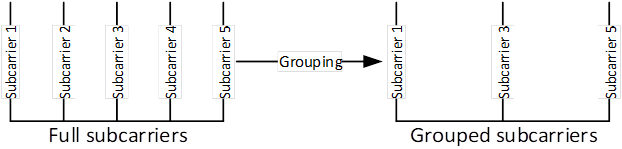
Figure 1
[1] It should be noted that full subcarriers is better than grouped subcarriers for sensing theoretically. This can be easily understood if we think about the CRLB (Cramér-Rao Lower Bound), which is the theoretical bound describes the lower bound of MSE in the parameter estimation. The CRLB of delay can be calculated with the following equation.
![]()
For simplicity, we are discussing a single antenna case and the ![]() in the above equation is the SNR level at the receiving antenna.
in the above equation is the SNR level at the receiving antenna. ![]() is the root mean square bandwidth of the signal used for sensing and can be calculated with equation
is the root mean square bandwidth of the signal used for sensing and can be calculated with equation ![]() . It is easy for us to know that the
. It is easy for us to know that the ![]() of full subcarriers is greater than
of full subcarriers is greater than ![]() of grouped subcarriers, which means the CRLB of full subcarrier is lower than that of the grouped subcarriers. That is the theoretical reason why full subcarriers is better than grouped subcarrier in sensing.
of grouped subcarriers, which means the CRLB of full subcarrier is lower than that of the grouped subcarriers. That is the theoretical reason why full subcarriers is better than grouped subcarrier in sensing.
[2] Based on the feedback procedure of frequency domain CSI, the full subcarrier CSI is estimated and obtained at sensing receiver. Then the full subcarrier CSI will be grouped and fed back to sensing transmitter, which means the sensing transmitter can perform sensing only with the grouped subcarriers CSI.
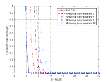
In the simulation of DCN 21/1288, the (T)CIR we presented is generated with full subcarrier rather than grouped subcarrier. The result indicates that the sidelobe generated with full subcarrier is lower than the sidelobe generated with grouped subcarrier. The sidelobe level is very important in sensing for further detection and parameter estimation. One simulation result from 21/1288 is pasted here as figure 2.
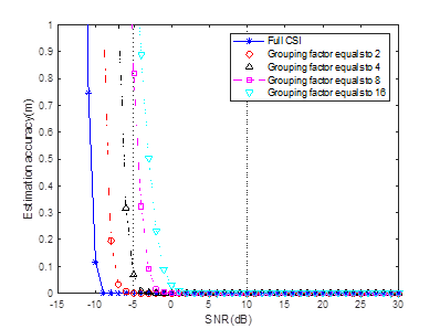
Figure 2
In figure 2, the x-axis is the SNR level and y-axis is the estimation accuracy. The simulation results show that the estimation accuracy improves with the SNR increases. More important is that, the results clearly indicate that the sensing performance decreases with grouping number Ng increases. The simulation results are consistent with the theoretical analysis we mentioned above.
[3] It is the feedback overhead reduction. The feedback overhead of TICR is much smaller than the Ng can be used for now(Ng can be further increase for overhead reduction but the performance will further reduced, as the analysis listed above).
Based on the advantages described above on, TCIR could achieve better performance (and lower overhead) if the target is located in the feedback subset of the CIR. The problem that how the subset of CIR should be selected is explained in the answer for Question 3.
2. The first sub-bullet of the motion text (“Calculating the CIR (time domain) from frequency domain CSI through IDFT(usually, IFFT)” ) appears an implementation. Is your intention to mandate this operation at sensing receivers?
[Rui Du] I am not preventing any other methods or techniques that can be used to generate CIR. If you have any potential suggestion, we could discuss it.
Based on my understanding, FFT/IFFT is definitely a good choice based on two reasons.
[1] FFT/IFFT is widely adopted in the wireless communication already due to its low complexity and some other advantages, it is a good choice that we can reuse it.
[2] FFT/IFFT is an linear integral transformation. The adoption of FFT/IFFT usually won’t add any distortion to the signal and remain the information that is needed for further sensing processing. For example, angle information can be estimated based on the multiple CIRs (generated from frequency domain CSI by IFFT) from multiple antennas.
3. In the second sub-bullet of the motion, you have “complex samples corresponding to the range of interest of the entire CIR”. I am not sure how the “entire CIR” is defined and if it can be defined consistently among different sensing receivers. In addition, from your early contributions, it clears to me that this set of complex numbers (i.e., PDP?) may vary a lot depending on the algorithm at the sensing receiver (e.g., grouping size and timing relationship among those numbers). So, the question is how you can guarantee the consistency of the measurements from different sensing receivers.
[Rui Du] In the contribution, the entire CIR is defined as the output of IFFT of the full subcarrier CSI. And as we stated in the contribution, CIR may be affected by the synchronization offset. An example is shown in figure 3, solid line is the amplitude of the 1st CIR and dash line is the amplitude of the 2nd CIR. The amplitude of the 1st CIR and 2nd CIR may be different because the time synchronization is performed per PPDU. The important thing is that the relative delay Δt between the 1st peak and 2nd peak remain constant in different CIRs in a sensing device within coherent time. Physically, Δt represents the propagation difference between LOS and reflection path (R1+R2) as figure 4 shows. So, with some ideas borrowed from 60GHz, the consistency of the measurements ((T)CIRs) from single device can be achieved by selecting the subset with a reference point (e.g. the tap with largest amplitude). That means, no matter how CIRs is affected by the synchronization offset, the subset can be chosen around the tap with largest magnitude, and the consistency can be achieved.
I am a little bit confused with the ‘consistency of measurements from different receivers’ ? Can you explain why we need the consistency from different receivers ? So I can do further clarifications.
If you mean ‘how can we fuse the results from different sensing receivers ?’ The answer is that this is another complicated problem which is not related to what I proposed. But, please bear in mind that, If we have multiple devices in the sensing, the consistency of measurements per device can be achieved by the method we mentioned above. The CIRs measured at multiple receivers are different due to the different positions of receivers (e.g. assuming on transmitter and multiple receiver in figure 5), because they are coming from different sensing links. The important thing is to make the measurement per device consistent.
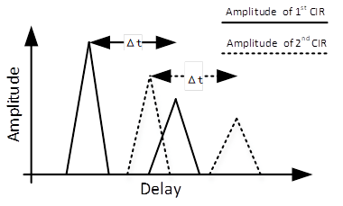
Figure 3
Figure
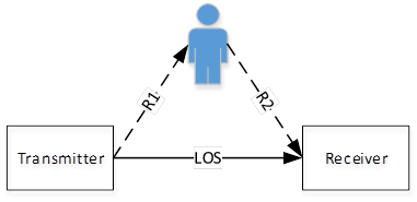
Figure 4
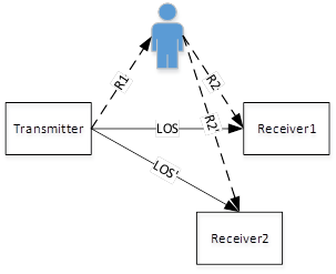
Figure 5
In general, I believe we should not ask sensing receivers, which need to feedback sensing measurement results, to process CSI for a measurement that we cannot ensure the consistency of its meaning and reference value over time and among different sensing devices.
[Rui Du] Based on my understanding, it is easy for the measurements to achieve consistency for each individual device with some selection rules mentioned above. And what I proposed here is trying to maximally utilize the signal for sensing with a very simple processing.
[Rui Du] Please let me know if you have any further comments or questions.
Best regards,
Ray
From: durui (D) <000017788cb650b9-dmarc-request@xxxxxxxxxxxxxxxxx>
Sent: Tuesday, January 11, 2022 10:44 PM
To: STDS-802-11-TGBF@xxxxxxxxxxxxxxxxx
Subject: [STDS-802-11-TGBF] Discussion for 20/1288 (TCIR) and the motion
Dear all,
I am sending this email to initiate a discussion on the contribution 21/1288 Truncated Power Delay Profile(Truncated Channel Impulse Response) - follow up and motion 49 I ran yesterday.
Actually, I already tried to collect as much opinions as possible from the group member before the motion, and I thought I’ve discussed thoroughly with the group members who feedback their concerns or questions. I was surprised with the motion results.
Hence, I would like to discuss if there is any further concerns. Please feel free to let me know (by 11bf reflector or private email) your thoughts and any suggestions for the contribution and the motion.
Best wishes,
Rui Du
To unsubscribe from the STDS-802-11-TGBF list, click the following link: https://listserv.ieee.org/cgi-bin/wa?SUBED1=STDS-802-11-TGBF&A=1
To unsubscribe from the STDS-802-11-TGBF list, click the following link: https://listserv.ieee.org/cgi-bin/wa?SUBED1=STDS-802-11-TGBF&A=1
To unsubscribe from the STDS-802-11-TGBF list, click the following link: https://listserv.ieee.org/cgi-bin/wa?SUBED1=STDS-802-11-TGBF&A=1
To unsubscribe from the STDS-802-11-TGBF list, click the following link: https://listserv.ieee.org/cgi-bin/wa?SUBED1=STDS-802-11-TGBF&A=1
To unsubscribe from the STDS-802-11-TGBF list, click the following link: https://listserv.ieee.org/cgi-bin/wa?SUBED1=STDS-802-11-TGBF&A=1
To unsubscribe from the STDS-802-11-TGBF list, click the following link: https://listserv.ieee.org/cgi-bin/wa?SUBED1=STDS-802-11-TGBF&A=1
To unsubscribe from the STDS-802-11-TGBF list, click the following link: https://listserv.ieee.org/cgi-bin/wa?SUBED1=STDS-802-11-TGBF&A=1