Hi Rui,
I personally think we had a very thorough discussion on TCIR in last month (actually more than 1 month). Thank you again for all the questions and comments.
With some offline discussions, I think other members who care TCIR are already clear about this idea. And since I didn’t get any other further questions or comments, I guess the group members are
clear about this idea.
I am planning to run the SP and motion again recently, if you have any further questions or comments, please let me know.
And also, we can have a call if you think it is needed.
Best wishes,
Rui Du
发件人: durui (D)
发送时间: 2022年2月10日
14:10
收件人: 'Rui Yang' <Rui.Yang@xxxxxxxxxxxxxxxx>
抄送: STDS-802-11-TGBF@xxxxxxxxxxxxxxxxx
主题: 答复: [STDS-802-11-TGBF]
答复: [STDS-802-11-TGBF] 答复: Discussion for 20/1288 (TCIR) and the motion
Hi Rui,
Thanks for your email.
Let me try again and please find my answer inline as follows.
If it is necessary, I do believe we need a call to make you more clear about this proposal.
Btw,
[1] attached pleased find a
contribution in 802.15.4ab(link:https://mentor.ieee.org/802.15/dcn/22/15-22-0066-02-04ab-link-budget-analysis-and-cir-reporting-for-uwb-rf-sensing.pptx).
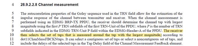
The selecting rule of the CIR in slide 12-14 is the
same with what we are discussing now (using the strongest tap as the reference point and
selecting some taps around the reference points).
[2] similar rule is already adopted in 11ay(as the figure attached follows, you can also find it in 11ay draft).
Best wishes,
Rui Du
发件人: Rui Yang [mailto:Rui.Yang@xxxxxxxxxxxxxxxx]
发送时间: 2022年2月9日
22:05
收件人: durui (D) <ray.du@xxxxxxxxxx>
抄送:
STDS-802-11-TGBF@xxxxxxxxxxxxxxxxx
主题: RE: [STDS-802-11-TGBF]
答复: [STDS-802-11-TGBF]
答复: Discussion for 20/1288 (TCIR) and the motion
Hi Rui
Hope you enjoyed the New Year break last week.
Again, thank you for very detailed reply to my questions. I think I have a good understanding of the approach you proposed.
Based on what we have discussed and the information you’ve provided, I have to say that I still don’t think it is a good idea to feed back TCIR for the following reasons:
1)
The recipient of TCIR can’t clearly understand what those numbers (taps) are. The true interpretation of those numbers depends on the environment or the channel.
[Rui Du] Again,
the problem of interpretation is not caused by the TCIR
(as previous discussion). Same problem happens no matter which kind of feedback type is adopted.
It is very unrealistic to assume the first tap corresponding to the LoS. This is the consistency issue I mentioned at very beginning of this discussion.
[Rui Du] As I mentioned in previous email, in all the contributions/discussions, I am assuming
in LOS case,
the tap with largest magnitude is the LOS path (with high probability) and should be selected as the reference point for TCIR subset selection.
By the way, it is not necessarily true that the strongest tap corresponds to the LoS path. Many field test data have shown it.
[Rui Du] I think you still misunderstand. I am not
assuming the strongest tap always corresponds to the LOS path in any cases.
In
LOS case (when LOS is not blocked), I am assuming is that the strongest tap is LOS with high probability. So, in the LOS case, the strongest tap is a good reference point.
In
NLOS case (when LOS is blocked), of course there is possibility that the strongest tap is not the LOS in NLOS cases, but the tap with largest magnitude it is still the
best way we can choose.
We’ve discussed it in previous email and I am pasting part of the email here again.
I list 3 typical NLOS cases here (we can discuss if there are more cases) for further discussion and let’s assume the sensing PPDU can be decoded and CSI can be estimated in all
NLOS cases.
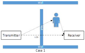
[Case 1]: All propagation paths (including ‘(attenuated) LOS’ and signal reflected from target) are attenuated.
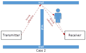
[Case 2]: There is no ‘(attenuated) LOS’ signal, there is a very strong reflection path and a weak path reflected from the target human.
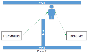
[Case 3]: There is no ‘(attenuated) LOS’ signal, the only propagation path is the reflection path from target, or the strongest path comes from the target.
To answer your question clearly, I am trying to answer it based on these 3 cases.
Can TCIR feeds back the information needed in sensing (e.g. information of the target human) in NLOS cases with the proposed selecting rules discussed previously ?
The answer is
Yes.
[Case 1]: Both ‘(attenuated) LOS’ and signal reflected from target are attenuated by the wall. In this case, both signal is attenuated and the largest amplitude tap is still the
‘(attenuated) LOS’ signal and the target human’s information is included with the proposed selecting rule.
[Case 2]: This case can be treated as there is a virtual transmitter at the reflecting point on the wall. With the same selection rule, the target human’s information also can be
selected correctly.
[Case 3]: In this case, the reference tap (the tap with largest amplitude) represent the target human, if the same rule can be adopted to select the feedback subset. Target human’s
information also can be included.
So, for all NLOS cases described above, target human’s information can be selected correctly with the proposed rule. Some, sensing applications (e.g. present detection, etc.) still
can be realized.
2)
It is true that it is not easy to detect LoS/NLoS and some other complex channel information, but it is still possible with more sophisticated and application dependent
algorithms. Typically, those are the jobs for more powerful devices (e.g., AP) to deal with.
[Rui Du] If you have more information about these kind of ‘algorithms’ please share with me. If there is some algorithms, we may try to analysis if it needs to be perform in AP.
BTW, we are not limiting the TCIR only can be performed at STAs, it is performed at the sensing receiver who need to feedback the sensing measurement and the sensing receiver also can be AP in 11bf.
If the sensing receiver process the CSI by removing certain information (e.g., truncation), it would be difficult for those devices or algorithms to extract
the information they need. I believe this is the same concern as Ron mentioned in another email thread.
[Rui Du]
1. With
analysis, simulation and even demo testing with measurement data,
we have already shown that TCIR really works!
2.
As we discussed in previous email, the truncation is applied in time domain, in which the information is highly redundant. And, even the entire CIR could be got by the sensing imitator (or other
devices who need it), the sensing initiator will also truncate the CIR to reduce the following computation complexity. And when the initiator truncates the CIR, same rules will be adopted.
3. TCIR is an optional feedback type, and the initiator could choose to use it or not.
By the way, after discussion with Ron, I think Ron understand TCIR now and I’m waiting for his further comments if he has.
Best regards,
Ray
From: durui (D) <ray.du@xxxxxxxxxx>
Sent: Thursday, January 27, 2022 1:44 AM
To: Rui Yang <Rui.Yang@xxxxxxxxxxxxxxxx>;
STDS-802-11-TGBF@xxxxxxxxxxxxxxxxx
Subject: 答复: [STDS-802-11-TGBF]
答复: [STDS-802-11-TGBF]
答复: Discussion for 20/1288 (TCIR) and the motion
Hi Rui,
Thanks for your email and I think you raise a very good question here.
Please find my answers inline as follows.
Best wishes,
Rui Du
发件人: Rui Yang [mailto:Rui.Yang@xxxxxxxxxxxxxxxx]
发送时间: 2022年1月27日
6:29
收件人: durui (D) <ray.du@xxxxxxxxxx>
抄送:
STDS-802-11-TGBF@xxxxxxxxxxxxxxxxx
主题: RE: [STDS-802-11-TGBF]
答复: [STDS-802-11-TGBF]
答复: Discussion for 20/1288 (TCIR) and the motion
Hi Rui Du,
Thank you for the clarification.
Regarding your response
below, in monostatic scenario, no feedback from sensing receiver is needed since sensing Tx and Rx are in the same device. In bistatic scenario, it looks like you assumed the first tap corresponds
to LOS, which can’t be always true in general.
[Rui Du] In the simulation, the ‘first tap’ is assumed to be LOS just for simplicity. But in all the contributions/discussions, I am assuming
the tap with largest magnitude is the LOS path and should be selected as the reference point
for TCIR subset selection in LOS case.
Without LOS information or a common reference (time or location) between a sensing transmitter and sensing receivers, different reflection environments may generate the same/similar
TCIR (e.g., two taps only for a range of interest) for each sensing receiver or among sensing receivers at different locations. In this case, the device (sensing Tx or initiator) that receives and processes such a feedback can’t tell the difference. This is
one of the consistency issues I mentioned before.
[Rui Du]
I list 3 typical NLOS cases here (we can discuss if there are more cases) for further discussion and let’s assume the sensing PPDU can be decoded and CSI can be estimated in all NLOS cases.
[Case 1]: All propagation paths (including ‘(attenuated) LOS’ and signal reflected from target) are attenuated.
[Case 2]: There is no ‘(attenuated) LOS’ signal, there is a very strong reflection path and a weak path reflected from the target human.
[Case 3]: There is no ‘(attenuated) LOS’ signal, the only propagation path is the reflection path from target, or the strongest path comes from the target.
To answer your question clearly, I am trying to answer it from 3 perspectives.
1.
Can TCIR feeds back the information needed in sensing (e.g. information of the target human) in NLOS cases with the proposed selecting rules discussed previously ?
The answer is
Yes.
[Case 1]: Both ‘(attenuated) LOS’ and signal reflected from target are attenuated by the wall. In this case, both signal is attenuated and the largest amplitude tap is still the
‘(attenuated) LOS’ signal and the target human’s information is included with the proposed selecting rule. Btw, the
selecting
rule is using the
tap
with
largest
amplitude as the
reference
point and
selecting some taps around the reference point according to the range of interest.
[Case 2]: This case can be treated as there is a virtual transmitter at the reflecting point on the wall. With the same selection rule, the target human’s information also can be
selected correctly.
[Case 3]: In this case, the reference tap (the tap with largest amplitude) represent the target human, if the same rule can be adopted to select the feedback subset. Target human’s
information also can be included.
So, for all NLOS cases described above, target human’s information can be selected correctly with the proposed rule. Some, sensing applications (e.g. present detection, etc.) still
can be realized.
2.
The other question is that how can we localize the target human in NLOS cases ?
This is a very classical problem in
NLOS sensing which has been investigated for decades.
The answer is it is very hard to achieve the localization of target in NLOS cases without any other additional information. Usually, if some additional information(e.g. the structure
of the house, etc.) can be got, the localization can be achieved. Further information can be found in bullet 3 (the following one).
3.
Assuming full subcarrier CSI (Ng=1) is fed back to transmitter. Will the problem for target human localization in NLOS be solved?
The answer is
No, because this is a
common problem no matter what kind of feedback is adopted.
Let’s discuss a ‘ideal’ case that full CSI (Ng=1) is fed back from each individual receiver. To estimate the delay/range information, full CSI can be used to generate the ‘full CIR’
for further range estimation.
For each individual ‘full CIR’, some peaks/taps (representing the propagation paths) will be observed. But these multiple ‘full CIR’ are not same, because they represent the channel
observed by different receivers ! Even with the ‘full CIR or full CSI (Ng=1)’, it is still hard to know
if the first peak in ‘full CIR’ represents the LOS path or not.
In sensing, further signal processing will also be applied
around the taps/peaks (representing the propagation paths) in ‘full CIR’
to
extract
potential sensing information. Please note that under this condition,
‘full CIR’ from different receivers also may have same/similar profile around these taps/peaks (which is the TCIR)! But
we are not sure if the first peak in ‘full CIR’ is the LOS or not. So, how can we use these ‘full CIR’ or full CSI (Ng=1) from different receivers for sensing and achieve consistency ? Same question appears here.
In summary, the problem of consistency realization (or fusion) of feedbacks from different receivers is not caused by TCIR ! It is a common problem in NLOS sensing, no matter
what kind of feedback type is adopted.
Actually, I think this is a problem not only for sensing but also for positioning (e.g. 11az). Similar problem happens for 11az in NLOS cases (please correct me if I understand it
wrong). Actually, it is very hard for the device to judge if the received signal comes from LOS. Although polarization switching has been adopted at 60 GHz for LOS assessment, I am not very sure about its performance at sub 7GHz. So, 11az usually treats the
first path received at receiver as the signal comes from LOS and use it’s timestamp for further round trip time (RTT) calculation. In NLOS cases, if the first path received at receiver is a signal reflected from other paths, it is hard to positioning the device
accurately.
Best regards,
Ray
From: durui (D) <ray.du@xxxxxxxxxx>
Sent: Monday, January 24, 2022 9:02 PM
To: Rui Yang <Rui.Yang@xxxxxxxxxxxxxxxx>;
STDS-802-11-TGBF@xxxxxxxxxxxxxxxxx
Subject: 答复: [STDS-802-11-TGBF]
答复: [STDS-802-11-TGBF]
答复: Discussion for 20/1288 (TCIR) and the motion
Hi Rui,
Thanks for your email and please find my answers inline as follows.
Best wishes,
Rui Du
发件人: Rui Yang [mailto:Rui.Yang@xxxxxxxxxxxxxxxx]
发送时间: 2022年1月25日
4:49
收件人: durui (D) <ray.du@xxxxxxxxxx>
抄送:
STDS-802-11-TGBF@xxxxxxxxxxxxxxxxx
主题: RE: [STDS-802-11-TGBF]
答复: [STDS-802-11-TGBF]
答复: Discussion for 20/1288 (TCIR) and the motion
Hi Rui Du,
Thank you for the clarifications. I have a few follow up questions in the email below.
Best regards,
Ray
From: durui (D) <000017788cb650b9-dmarc-request@xxxxxxxxxxxxxxxxx>
Sent: Monday, January 24, 2022 3:04 AM
To: STDS-802-11-TGBF@xxxxxxxxxxxxxxxxx
Subject: [STDS-802-11-TGBF] 答复: [STDS-802-11-TGBF]
答复: [STDS-802-11-TGBF]
答复: Discussion for 20/1288 (TCIR) and the motion
Hi Rui,
Thanks for your email and please find my answers inline as follows.
Best wishes,
Rui Du
发件人: Rui Yang [mailto:Rui.Yang@xxxxxxxxxxxxxxxx]
发送时间: 2022年1月22日
6:17
收件人: durui (D) <ray.du@xxxxxxxxxx>
抄送:
STDS-802-11-TGBF@xxxxxxxxxxxxxxxxx;
Ron Porat <ron.porat@xxxxxxxxxxxx>
主题: RE: [STDS-802-11-TGBF]
答复: [STDS-802-11-TGBF]
答复: Discussion for 20/1288 (TCIR) and the motion
Dear Rui Du,
Could you explain how you defined “estimation accuracy”, shown in the figures you attached?
[Rui Du] It is true that the range resolution of 20 MHz is 7.5m in the simulation. But please note that the definition of resolution is different with accuracy (both of them are key indicators
for a sensing systems).
The resolution is defined as the ability to separate two targets.
The accuracy is defined as how good a target can be estimated, it is usually defined as the RMSE/MSE between the estimated value and ground truth.
Btw, If you have a look at the 11bf use case document, you could find there are accuracies and separations (resolution) for each individual use case. And usually, the value of accuracy is (much)
smaller than that of the separation(resolution).
![]()
[RY] My question is about your definition of “estimation accuracy”.
[Rui Du] I used the typical definition of ‘estimation accuracy’ describe above.
‘The accuracy is defined as how good a target can be estimated, it is usually defined as the RMSE/MSE between the estimated value and ground truth.’
In 20MHz channel bandwidth case, as you used in your simulation, the range resolution is 7.5 meters. If the “estimation accuracy” is defined as the difference between true location
and estimated location of an object, how can you get such a high estimation accuracy (~0 meter in high SNR) without knowing the location of the object in advance? Thanks.
[Rui Du] The y axis should be labeled
as estimation accuracy (range cell) rather than
estimation accuracy (m).
[RY] Could you explain what is “range cell” and, for example, if estimation accuracy = 0.1 “range cell” (replacing “m” to “range cell” in your figure), what does it mean?
You may misunderstand my last question above. Let me try another way: in your PDP plots in slide 6 of 21/1288r4, what does “0” value in Range mean? In other word, what is the
reference of “range”?
[Rui Du] Range cell is a typical sensing term and it is same with ‘range resolution’. As I described in last email, when estimation accuracy (cell) achieves
0, it means the target is detected at the range cell/range resolution where ground truth located. In the simulation, at each SNR level, 20000 time independent simulations are conducted, and an ‘estimated range’ and corresponding ‘range accuracy
(cell) ’ can be got for each individual simulation. The ‘estimation accuracy (cell)’ in the simulation represents the mean value of accuracies from these 20000 simulations. 0.1 is the mean accuracy of 20000 times simulations, and it means the mean accuracy
(as defined above) at this SNR level is 0.1 range cell/resolution.
Ok, now I get your question clearly, thank you for the rephrasing. Please find my answer as follows.
In the simulation, we are considering a simple case in which transmitter and receiver are fully synchronized, the ‘0’ in range is the time
(could be transformed to range with tie ) when sensing PPDU is transmitted.
In real systems, this is could be solved with the information of LOS. Some commons methods are listed here, for example,
In monostatic sensing, the coupling between transmitting antenna and receiving antenna could generate a peak with very large value in measured
CIR, this peak usually is regarded as ‘0’ in range.
In bistatic sensing, it is very hard to get range ‘0’ precisely with commercial WLAN system. And, the CIR will also be affected by some other
effects (i.e. synchronization offset, etc.). Although the range ‘0’ is not available in this case, but as we discussed in previous email, the propagation difference between LOS and reflection path remain the same.
Thanks very much for the important question, and I will correct it in the following discussions/contributions.
In this simulation, we are only evaluating the sensing performance at range cell level. So, when accuracy(cell) reaches 0, it means that the target is detected correctly within the range cell
where ground truth located. And of course, further signal processing could be applied to analysis the sensing accuracy(m) it could achieve within a resolution cell (limited by CRLB, and a similar performance gap between TCIR and grouped CSI still existing).
But, please note that,
even with 20MHz, you are still able to achieve very high sensing accuracy (m) (~0 meter) at high SNR level when target is already separated, if some estimator (e.g. ML) is adopted. Many conclusions can be found from
relevant academic papers.
[Rui Du] Btw, if you want to estimate a target, the first thing you need to do is create a target in your simulation. Definitely the parameters of the target (ground truth) are known in the simulation,
because these parameters are adopted to simulate target. The signal is reflected by the target and received at the receiver and further processing is applied to estimate the target’s parameter.
This is a common way to evaluate the sensing performance , both for simulation and commercial systems.
For commercial system, the ground truth (e.g. information from GPS, etc.) is also needed during the test to evaluate the sensing performance.
Then, the system will be applied in actual scenarios. And of course in the practical scenarios, you may not have the actual ground truth. However, the system detection performance has already
been validated!
In the simulation, we can achieve very good performance at high SNR level. In actual systems, it is usually very hard to achieve this kind of performance because of non-ideal effects (e.g. clutter,
impairment of systems, RCS fluctuation, etc.). Simulations can take into account these non-ideal effects to a certain extend. But it might be difficult to completely model the real world non-ideal effects in simulations!
But please note although the sensing performance will reduce in real system, the
performance gap between TCIR and grouped CSI still existing ! This is clearly proved by the theoretical bound (CRLB).
Best regards,
Ray
From: Ron Porat <000009a0da80e877-dmarc-request@xxxxxxxxxxxxxxxxx>
Sent: Friday, January 21, 2022 2:25 PM
To: STDS-802-11-TGBF@xxxxxxxxxxxxxxxxx
Subject: Re: [STDS-802-11-TGBF] 答复: [STDS-802-11-TGBF]
答复: Discussion for 20/1288 (TCIR) and the motion
Hi Rui,
Thanks very much for the quick answers. At this point I don’t recall the exact discussions in 11ac MU-MIMO feedback.
I generally think that an SNR range>10dB is more applicable to us in reality and negative SNR as shown in the plots below are of no interest. Same for 20MHz BW, to the extent that
it makes a difference it’s better to see results for 160MHz BW or at least 80MHz, at the least you will get more feedback tones even with Ng=16 for 160MHz BW.
In addition with frequency domain feedback the sensing application can calculate time domain if it so desires.
Also, I’m not following why range estimation accuracy is the metric you chose for a sensing scheme that looks at channel variation.
Also, if feedback overhead is a concern then sending an NDP is very efficient.
Thanks,
Ron
From: durui (D) <000017788cb650b9-dmarc-request@xxxxxxxxxxxxxxxxx>
Sent: Friday, January 21, 2022 3:49 AM
To: STDS-802-11-TGBF@xxxxxxxxxxxxxxxxx
Subject: [STDS-802-11-TGBF] 答复: [STDS-802-11-TGBF]
答复: Discussion for 20/1288 (TCIR) and the motion
Hi Ron,
Thanks for your email and please find my answers inline as follows.
We can have an online discussion if needed.
Best wishes,
Rui Du
发件人: Ron Porat [mailto:ron.porat@xxxxxxxxxxxx]
发送时间: 2022年1月21日
2:32
收件人: durui (D) <ray.du@xxxxxxxxxx>;
STDS-802-11-TGBF@xxxxxxxxxxxxxxxxx
主题: RE: [STDS-802-11-TGBF]
答复: Discussion for 20/1288 (TCIR) and the motion
Hi Rui Du,
Can you compare TCIR to decimated frequency domain with the
same total number of complex samples fed back?
[Rui Du] Attached please find the simulation results for the sensing performance of two different targets (a strong target and a weak target).
In the simulation, the legend ‘Full CSI’ represent TCIR and has the
same number of complex samples with the legend ‘grouping factor equals to 16’(which represent Ng-16 is adopted during the grouping).
Please note that the simulation is just an example and the feedback size of TCIR can be further reduced according to the applications. For example, only 1 tap (the tap with largest magnitude)
is used in the experimental validation for the finger tracking (the results can be find in DCN 0660/1288).
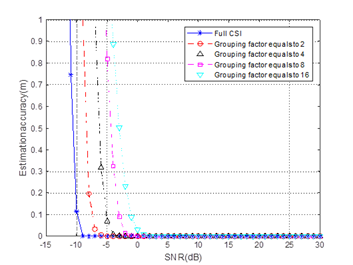
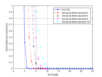
In the simulation the x-axis is SNR and y-axis is the range estimation accuracy (defined as the root mean square error between the estimated range and ground truth). Both results (sensing for
strong target and weak target) indicate that the estimation accuracy based on TICR (legend with ‘full CSI’) is better than the sensing performance based on
same numbers frequency CSI (legend with ‘grouping factor equals to 16’).
Also, why would the Rx work harder to generate TCIR if frequency domain is good enough? FYI already in 11ac (e.g 1131) time domain was discussed as channel feedback but was not accepted.
[Rui Du] This is a very good question and I think we need to discuss how can we define ‘good enough’.
First of all, the simulations have shown that the
sensing performance of TCIR is better than that of grouped CSI. This also can be explained by the CRLB I mentioned in previous email. Experimental validation of TCIR for finger
tracking also has been presented in my previous contributions. So, based on the above mentioned, I personally think that TCIR could achieve better sensing performance than grouped CSI.
Maybe another relevant question here is ‘if frequency domain CSI is good enough already’ ?
To be honest, I am not sure at this stage. In WLAN sensing, the most important information we want is the feature(s) of intended targets in a given environment. In different applications, the
target could be a human being , a pet or even a hand (i.e. hand gesture recognition). So the signal reflected from the target could be very small and also much smaller than LOS signal (this is quite different with communication which mainly relies on the LOS
signal in most cases). So, if we want to sense a unknown target (which may have very low SNR), definitely it is good to adopt a method that has ‘better performance’ rather than a method has ‘good performance’.
Also, many WLAN sensing academic papers has been published based on the CSI estimated at the receiver. To achieve better performance, the researchers always would like to use all the subcarriers
rather than part of the subcarriers.
Thanks for your information. But I think the advantages of TCIR in sensing is different with that in communication. If possible, could you please share
me more information about why it was not accepted in communication ?
Regards,
Ron
From: durui (D) <000017788cb650b9-dmarc-request@xxxxxxxxxxxxxxxxx>
Sent: Thursday, January 20, 2022 12:35 AM
To: STDS-802-11-TGBF@xxxxxxxxxxxxxxxxx
Subject: [STDS-802-11-TGBF] 答复: Discussion for 20/1288 (TCIR) and the motion
Hi Rui,
Sure, please take your time and also please find my answers inline as follows.
Best wishes,
Rui Du
发件人: Rui Yang [mailto:Rui.Yang@xxxxxxxxxxxxxxxx]
发送时间: 2022年1月19日
7:44
收件人: durui (D) <ray.du@xxxxxxxxxx>
抄送:
STDS-802-11-TGBF@xxxxxxxxxxxxxxxxx
主题: RE: Discussion for 20/1288 (TCIR) and the motion
Dear Rui Du,
Thank you for your long responding email. If you don’t mind, I will try to address your comments/questions in a few days.
Meantime, may I ask if the result with “Full CSI” in Figure 2 corresponds to the full PDP or full CIR without truncation?
[Rui Du] The legend ‘Full CSI’ in the simulation in DCN 1288 represents truncated CIR (TCIR). In the simulation, two targets are located at 30m and 120m, respectively. The feedback size of TCIR
![]() , corresponding to the range of interest
, corresponding to the range of interest
![]() .
.
Please note that the parameter adopted in the simulation is just an example. According to the 11bf use case document, the maximum range for WLAN sensing is 20 meters
(i.e. store sensing). This means the feedback size of TCIR can be further reduced.
Do you have the results with different truncation length (different CIR feedback size)? Thanks.
[Rui Du] If the TCIR of can be
selected/truncated properly from
the ‘full CIR’, the increase of TCIR feedback size will not affect the sensing performance.
This is mainly because the sidelobe is affected by the number of subcarriers adopted during the transformation from frequency domain CSI to time domain CIR.
Since all the subcarriers are used by the IFFT to generate the ‘full CIR’, the ‘full CIR’ has low sidelobe levels, which will improve the sensing performance(as the simulations indicate). The only problem is that how the ‘full CIR’ can be truncated properly.
To select/truncate the TCIR properly, two criteria shall be met(as we described in the answer for Q3 in last email).
[1] The
index or position of the TCIR shall be selected properly. This can be solved by a good reference tap(e.g. the tap with largest amplitude).
[2] The
size of the TCIR shall be designed properly. As figure 3 in last email shows, the delay difference
Δt between the largest magnitude tap (reference tap) and the following tap represent the propagation delay difference between LOS path and reflected path. So, in different applications, the
size of the TICR is decided by the range of interest
in each application (the calculation method is also provided in my previous contribution).
For example, the range of interest can be set to 5 meters(or a little bit longer) if the information within 5 meters is need. The most important thing is that
the subset corresponding to 5 meters should be selected properly(as the criteria mentioned above), and any information beyond 5 meters is redundant in this case. If you want more information, you could adjust the range of interest according to your application.
In summary,
if the index/position of the TCIR is selected properly and the feedback size is enough to cover the range of interest, the increase of TCIR feedback size will not affect the sensing performance.
Please let me know if you have any further questions or comments.
Best regards,
Ray
From: durui (D) <000017788cb650b9-dmarc-request@xxxxxxxxxxxxxxxxx>
Sent: Sunday, January 16, 2022 9:12 PM
To: STDS-802-11-TGBF@xxxxxxxxxxxxxxxxx
Subject: [STDS-802-11-TGBF] 答复: Discussion for 20/1288 (TCIR) and the motion
Hi Rui,
Thanks for your comments and please find my answers inline as follows.
Best wishes,
Rui Du
发件人: Rui Yang [mailto:Rui.Yang@xxxxxxxxxxxxxxxx]
发送时间: 2022年1月13日
22:39
收件人: STDS-802-11-TGBF@xxxxxxxxxxxxxxxxx
主题: Re: [STDS-802-11-TGBF] Discussion for 20/1288 (TCIR) and the motion
Hi Rui Du,
Thank you for reaching out for comments. I apologize for missing your comment collection before.
Regarding the motion (#49) you proposed, I have a few concerns:
1.
It is not clear to me why the frequency domain CSI is not sufficient for sensing? If the concern is about feedback overhead, it would be better to consider additional reduction
based on the existing compressed CSI feedback. To generate the time domain CSI, the sensing receiver may need additional processing power, which would not be desirable.
[Rui Du] I am not very sure if the ‘compressed CSI feedback’ you mentioned is the
compressed beamforming matrix(the precoding matrix) in the main stream of 802.11 or not. But if you mean
compressed beamforming matrix here, the conclusion from TGbf is that
it cannot
be adopted for WLAN sensing directly, and that is the main reason why TGbf want to reuse the CSI matrix as a feedback type. If you have some ideas about how can we use compressed beamforming matrix in WLAN sensing,
I think the group will be very happy to discuss it.
So, in this email, I am only focus on the evaluation of
frequency domain CSI (CSI matrix) and
CIR for sensing, and explain the reasons why we need the CIR.
It is true that the feedback overhead of frequency domain CSI can be reduced with greater grouping factor Ng, but
(T)CIR could provide more advantages than overhead reduction! Here is one example figure (assuming 5 subcarriers) describes the approach of frequency
domain CSI grouping.
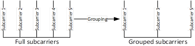
Figure 1
[1]
It should be noted that
full subcarriers is better than grouped subcarriers for sensing
theoretically. This can be easily understood if we think about the CRLB (Cramér-Rao Lower Bound), which is the theoretical bound describes the lower bound of MSE in the parameter estimation. The CRLB of delay can be calculated
with the following equation.
![]()
For simplicity, we are discussing a single antenna case and the
![]() in the above equation is the
SNR level at the receiving antenna.
in the above equation is the
SNR level at the receiving antenna.
![]() is the root mean square
bandwidth of the signal used for sensing and can be calculated with equation
is the root mean square
bandwidth of the signal used for sensing and can be calculated with equation ![]() . It is easy for us to know that the
. It is easy for us to know that the
![]() of full subcarriers
is greater than
of full subcarriers
is greater than ![]() of
grouped subcarriers, which means the CRLB of full subcarrier is lower than that of the grouped subcarriers. That is the
theoretical
reason why full subcarriers is better than grouped subcarrier in sensing.
of
grouped subcarriers, which means the CRLB of full subcarrier is lower than that of the grouped subcarriers. That is the
theoretical
reason why full subcarriers is better than grouped subcarrier in sensing.
[2]
Based on the feedback procedure of frequency domain CSI, the full subcarrier CSI is estimated and obtained at sensing receiver. Then the full subcarrier CSI will be grouped
and fed back to sensing transmitter, which means the sensing transmitter can perform sensing
only with the grouped subcarriers CSI.
In the simulation of DCN 21/1288, the (T)CIR we presented is generated with full subcarrier rather than grouped subcarrier.
The result indicates that the sidelobe generated with full subcarrier is lower than the sidelobe generated with grouped subcarrier. The sidelobe level is very important in sensing
for further detection and parameter estimation. One simulation result from 21/1288
is pasted here as figure 2.
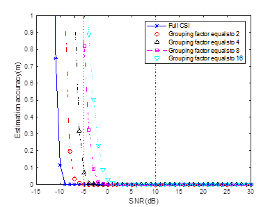
Figure 2
In figure 2, the x-axis is the SNR level and y-axis is the estimation accuracy. The simulation
results show that the estimation accuracy
improves with the SNR increases. More important is that, the results clearly indicate that the
sensing performance decreases with grouping number Ng increases. The
simulation results are consistent with the theoretical analysis we mentioned above.
[3]
It is the
feedback overhead reduction. The feedback overhead of TICR is much smaller than the Ng can be used for now(Ng can be further increase for overhead reduction but the performance will
further reduced, as the analysis listed above).
Based on the advantages described above on, TCIR could achieve
better performance (and lower overhead) if the target is located in the feedback subset of the CIR. The problem that how the
subset of CIR should be selected is explained in the answer for Question 3.
2.
The first sub-bullet of the motion text (“Calculating the CIR (time domain) from frequency domain CSI through IDFT(usually, IFFT)” ) appears an implementation. Is your
intention to mandate this operation at sensing receivers?
[Rui Du] I am
not preventing any other methods or techniques
that can be used to generate CIR. If you have any potential suggestion, we could discuss it.
Based on my understanding,
FFT/IFFT is definitely a good choice based on two reasons.
[1]
FFT/IFFT is widely adopted in the wireless communication already due to its low complexity and some other advantages, it is a good choice that we can
reuse it.
[2]
FFT/IFFT is an linear integral transformation. The adoption of FFT/IFFT usually
won’t add any distortion to the signal and remain the information that is needed for further sensing processing. For example, angle information
can be estimated based on the multiple CIRs (generated from frequency domain CSI by IFFT) from multiple antennas.
3.
In the second sub-bullet of the motion, you have “complex samples corresponding to the range of interest of the entire CIR”. I am not sure how the “entire CIR” is defined
and if it can be defined consistently among different sensing receivers. In addition, from your early contributions, it clears to me that this set of complex numbers (i.e., PDP?) may vary a lot depending on the algorithm at the sensing receiver (e.g., grouping
size and timing relationship among those numbers). So, the question is how you can guarantee the consistency of the measurements from different sensing receivers.
[Rui Du] In
the contribution, the
entire CIR is
defined as the
output of IFFT of the full subcarrier CSI.
And as we stated in the contribution, CIR may
be affected by the synchronization offset. An example is
shown in figure 3, solid line is the amplitude of the 1st CIR and dash line is the amplitude of the 2nd CIR. The amplitude of the 1st CIR and 2nd CIR may be different because the time
synchronization is performed per PPDU. The important thing is that the relative delay Δt between the 1st peak and 2nd peak remain
constant in different CIRs in a sensing device within coherent time. Physically,
Δt represents the
propagation difference between LOS and reflection path (R1+R2) as figure 4 shows. So, with some ideas borrowed from 60GHz, the consistency of the measurements
((T)CIRs) from single device can be achieved by selecting the subset with a reference point (e.g. the tap with largest amplitude). That means, no matter how CIRs is affected by the synchronization offset,
the subset can be chosen around the tap with largest magnitude, and the
consistency can be achieved.
I am a little bit confused with the ‘consistency of measurements from different
receivers’ ? Can you explain
why we need the consistency from different receivers
? So I can do further clarifications.
If you mean ‘how can we fuse the results from different sensing receivers ?’
The answer is that this is another complicated problem which is not related to what I proposed.
But, please bear in mind that, If we have
multiple devices in the sensing, the
consistency of measurements per device can be achieved
by the method we mentioned above. The CIRs measured at
multiple receivers are different due to the different positions of receivers (e.g.
assuming on transmitter and multiple receiver in figure 5), because they are
coming from different
sensing links. The important thing is to make the measurement per device consistent.
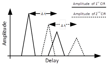
Figure 3
Figure
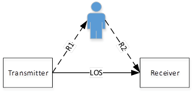
Figure 4
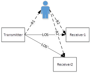
Figure 5
In general, I believe we should not ask sensing receivers, which need to feedback sensing measurement results, to process CSI for a measurement
that we cannot ensure the consistency of its meaning and reference value over time and among different sensing devices.
[Rui Du] Based on my understanding, it is
easy for the measurements to achieve
consistency for each individual device
with some selection rules mentioned above. And what I proposed here is
trying to maximally utilize the signal for sensing with a very
simple
processing.
[Rui Du] Please let me know if you have any further comments or questions.
Best regards,
Ray
From: durui (D) <000017788cb650b9-dmarc-request@xxxxxxxxxxxxxxxxx>
Sent: Tuesday, January 11, 2022 10:44 PM
To: STDS-802-11-TGBF@xxxxxxxxxxxxxxxxx
Subject: [STDS-802-11-TGBF] Discussion for 20/1288 (TCIR) and the motion
Dear all,
I am sending this email to initiate a discussion on the contribution 21/1288 Truncated Power Delay Profile(Truncated Channel Impulse Response) - follow up and motion 49 I ran
yesterday.
Actually, I already tried to collect as much opinions as possible from the group member before the motion, and I thought I’ve discussed thoroughly with the group members who
feedback their concerns or questions. I was surprised with the motion results.
Hence, I would like to discuss if there is any further concerns. Please feel free to let me know (by 11bf reflector or private email) your thoughts and any suggestions for the
contribution and the motion.
Best wishes,
Rui Du
To unsubscribe from the STDS-802-11-TGBF list, click the following link:
https://listserv.ieee.org/cgi-bin/wa?SUBED1=STDS-802-11-TGBF&A=1
To unsubscribe from the STDS-802-11-TGBF list, click the following link:
https://listserv.ieee.org/cgi-bin/wa?SUBED1=STDS-802-11-TGBF&A=1
To unsubscribe from the STDS-802-11-TGBF list, click the following link:
https://listserv.ieee.org/cgi-bin/wa?SUBED1=STDS-802-11-TGBF&A=1
To unsubscribe from the STDS-802-11-TGBF list, click the following link:
https://listserv.ieee.org/cgi-bin/wa?SUBED1=STDS-802-11-TGBF&A=1
To unsubscribe from the STDS-802-11-TGBF list, click the following link:
https://listserv.ieee.org/cgi-bin/wa?SUBED1=STDS-802-11-TGBF&A=1
To unsubscribe from the STDS-802-11-TGBF list, click the following link:
https://listserv.ieee.org/cgi-bin/wa?SUBED1=STDS-802-11-TGBF&A=1
To unsubscribe from the STDS-802-11-TGBF list, click the following link:
https://listserv.ieee.org/cgi-bin/wa?SUBED1=STDS-802-11-TGBF&A=1
To unsubscribe from the STDS-802-11-TGBF list, click the following link: https://listserv.ieee.org/cgi-bin/wa?SUBED1=STDS-802-11-TGBF&A=1